Home > Electrical & Electronics > Electrical Control System > ALSTOM N897066510E N897066010M AOVD N897066000A Controller Module

ALSTOM N897066510E N897066010M AOVD N897066000A Controller Module
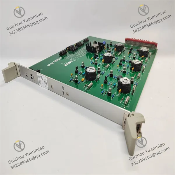
ALSTOM N897066510E N897066010M AOVD N897066000A Controller Module photo-1
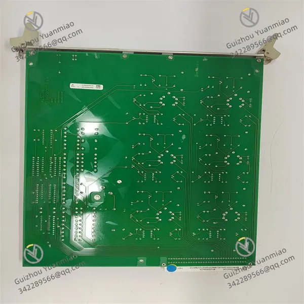
ALSTOM N897066510E N897066010M AOVD N897066000A Controller Module photo-2
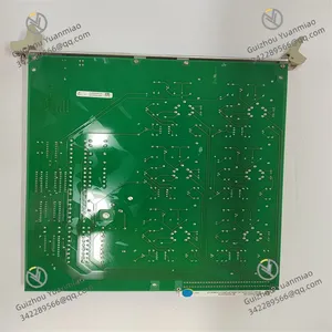
ALSTOM N897066510E N897066010M AOVD N897066000A Controller Module photo-3
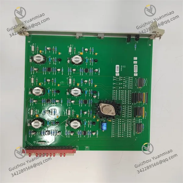
Negotiable MOQ: 1 Piece (Price negotiable depending on order volume and customization)
Key Specifications
Get Latest Price
Material:
Other, Global universal model
Condition:
Other, Global universal model
Task:
Other, Global universal model

Payment & Shipping
Payment Methods:
Port of Shipment:
China
Delivery Detail:
Delivery time depends on order quantity.
Material Other, Global universal model
Condition Other, Global universal model
Task Other, Global universal model
Mathematical Model Other, Global universal model
Signal Other, Global universal model
Customized Non-Customized
Structure Other, Global universal model
Operating temperature -40℃ to +70℃
Dimensions 100mm×100mm×70mm
ALSTOM N897066510E N897066010M AOVD N897066000A
Functional Features
  • High-performance Processing: Possibly equipped with a high-performance processor to enable fast data processing and complex control logic, capable of promptly handling sensor input signals and executing control commands.

  • High-precision I/O: Provides high-precision input/output interfaces to ensure signal accuracy and stability, enabling precise acquisition of analog signals or output of precise control signals.

  • Modular Design: Adopts a modular structure, facilitating user expansion and customization according to actual needs. Different functional modules can be flexibly combined to adapt to various project requirements.

  • Network Communication Capability: Supports multiple network communication protocols, such as Ethernet-related protocols and CANopen, to facilitate data exchange and integration with other devices or systems, and to easily integrate into the overall control system network.

  • High Reliability: Through strict testing and verification, it can operate stably in various harsh industrial environments, with capabilities such as anti-vibration and anti-electromagnetic interference, adapting to the severe working conditions in rail transit and other fields.

N897066510E N897066010M AOVD N897066000A (3)

Technical Parameters
  • Power Parameters: The input voltage may adapt to common vehicle-mounted or industrial voltages, such as DC 74V±20% or DC 110V±15%, etc. The power consumption may be about 10-20W under no load and about 30-50W under full load, depending on the module functions.

  • Communication Interfaces: May be equipped with about 2 Ethernet interfaces (10/100Mbps), supporting protocols such as EtherNet/IP, and may also have 1-2 RS-485 interfaces for Modbus RTU communication. The data transmission rate can reach up to 100Mbps (Ethernet) or 12Mbps (CANopen, etc.).

  • I/O Channels:

    • Digital input channels: Possibly 8-16 channels, optocoupler isolated.

    • Digital output channels: 4-8 channels, possibly relay or transistor output.

    • Analog input channels: Possibly 2-4 channels, with an accuracy of about 12 bits, capable of receiving 0-10V or 4-20mA signals.

    • Analog output channels: Possibly 1-2 channels, with an accuracy of about 10 bits, outputting 0-5V and other signals.

  • Environmental Parameters: The operating temperature range is generally -40℃ to +70℃, humidity is 5%-95% RH (non-condensing), the protection level may reach IP54, installed via DIN rail, and the external dimensions are approximately 100mm×100mm×70mm.

N897066510E N897066010M AOVD N897066000A (2)

Working Principle
  • Signal Acquisition and Processing: If N897066510E is similar to an input module, it may acquire external sensor signals (such as vehicle speed sensor signals, voltage and current signals, etc.) through optocoupler-isolated digital input channels or high-precision analog input channels. After analog signals are converted by A/D, they are stored in the module's internal cache, and then transmitted to the main control system or other related modules through the internal communication bus according to the set sampling frequency (such as 10kHz).

  • Control Command Output: If N897066010M is an output module, it will receive control commands from the main control system, drive external actuators through relay or transistor output channels (such as controlling the traction motor and braking device of the train). Some channels may support PWM modulation to achieve precise adjustment of parameters such as motor speed, and can monitor the output status through the feedback circuit to ensure the correct execution of commands.

  • Communication Interaction: The module has a built-in communication processor, supporting parallel processing of multiple protocol stacks. It can encapsulate the collected data into data frames according to the corresponding protocols (such as MVB, ProFINET, etc.) and send them out, while also being able to parse the command data frames received from other devices or systems to realize information interaction with the entire control system. It can serve as a slave node in the train network to receive commands from upper controllers, or as a master node to manage lower sub-modules.

  • Anti-interference and Safety Mechanisms: Adopts a multi-layer circuit board isolation design. The power supply part has an EMI filter circuit to prevent power supply fluctuations from interfering. The signal channels use anti-interference technologies such as magnetic isolation. A watchdog timer is built in to automatically restart when the module software encounters an abnormality, ensuring the safe operation of the system. It can also report faults hierarchically through LED light flashing and other methods to facilitate maintenance personnel in troubleshooting.

N897066510E N897066010M AOVD N897066000A (1)

Common Faults and Solutions1. Power-related Faults
Fault Phenomenon Possible Causes Solutions
Power indicator (PWR) not on 1. Input power not connected or voltage abnormal
2. Internal power fuse blown
3. Power management chip damaged
1. Use a multimeter to detect the input voltage (refer to the technical parameter range) and confirm the correct polarity
2. Open the module cover and replace the fuse (if replaceable)
3. Contact after-sales service to replace the power module
Abnormal power light flashing 1. Input voltage fluctuation exceeds the allowable range
2. Power filter capacitor aging
1. Check the stability of the power supply and install a voltage stabilizer
2. Return to the factory to replace the internal capacitor
2. Communication-related Faults
Fault Phenomenon Possible Causes Solutions
Network interface light not on 1. Poor contact or damage to the network cable
2. Incorrect IP address/port configuration
3. Physical layer chip failure
1. Replace the network cable or interface connector and plug it in again
2. Reset the communication parameters (such as IP, subnet mask) through the configuration software
3. Replace the module for testing, and return it to the factory for maintenance if it is invalid
Communication interruption (periodic disconnection) 1. Communication protocol conflict
2. Signal distortion caused by electromagnetic interference
3. Incompatible firmware version
1. Check the protocol configuration (such as Modbus, EtherNet/IP) to ensure consistency with the master device
2. Install a shielding layer for the cable or keep it away from interference sources
3. Upgrade to the official latest firmware
3. Analog Input/Output Faults
Fault Phenomenon Possible Causes Solutions
No response to analog input 1. Sensor signal open circuit or short circuit
2. Incorrect input channel range setting
3. Analog-to-digital converter (ADC) failure
1. Use an oscilloscope to detect the sensor output signal and replace the broken wire
2. Confirm the input range (such as 0-10V/4-20mA) through the configuration software
3. Use diagnostic tools to test the channel and replace the module if it fails
Abnormal analog output (such as constant value/jump) 1. Load exceeds the rated range
2. Digital-to-analog converter (DAC) failure
3. Poor grounding of the output cable
1. Check the load impedance to ensure it is within the technical parameter range
2. Send standard signals through the software for testing, and repair the DAC circuit if it is invalid
3. Re-ground or replace the shielded cable
4. Hardware Abnormalities and Environmental Faults
Fault Phenomenon Possible Causes Solutions
Abnormal module heating 1. Internal component short circuit (such as capacitor, chip)
2. Ambient temperature exceeds the rated range
3. Cooling holes blocked
1. After power off, touch the component surface to locate the heating point and replace the damaged component
2. Add a cooling fan or move to a ventilated environment
3. Clean the module surface dust to ensure good heat dissipation
Function abnormality due to vibration 1. Loose installation screws
2. Circuit board solder joint desoldering
1. Re-tighten the installation screws according to the torque requirements
2. Repair the desoldered solder joints, and Reinforcement the circuit board support if necessary
LED light error (such as 5 quick flashes) Hardware failure (such as memory, CPU abnormality) 1. Read the error code through special software (such as JTAG debugging interface)
2. If it is a memory failure, return to the factory to refresh the firmware or replace the chip
Product Tags: N897066510E , N897066010M , AOVD N897066000A

Send Inquiry to This Supplier

* Message
0/5000

Want the best price? Post an RFQ now!
Verified Business License
Business Type
Trading Company
Year Established
2014
Factory Size
1,000-3,000 square meters
Product Certifications
SA8000