Home > Electrical & Electronics > Electrical Control System > ALSTOM N897163510Q N897163050Q MODEM N897163100U Communication Interface Unit

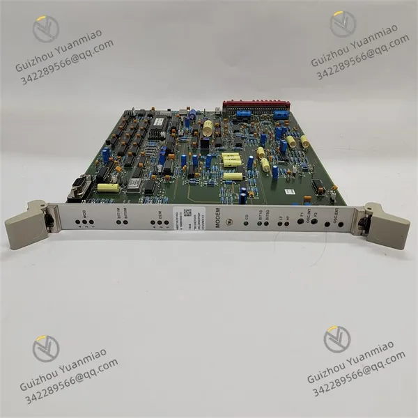
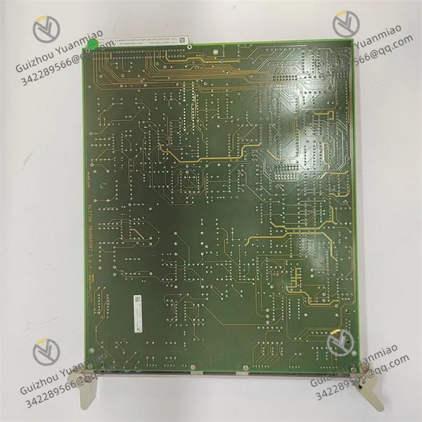
ALSTOM N897163510Q N897163050Q MODEM N897163100U Communication Interface Unit
ALSTOM N897163510Q N897163050Q MODEM N897163100U Communication Interface Unit photo-1
ALSTOM N897163510Q N897163050Q MODEM N897163100U Communication Interface Unit photo-2
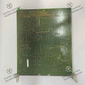
ALSTOM N897163510Q N897163050Q MODEM N897163100U Communication Interface Unit photo-3
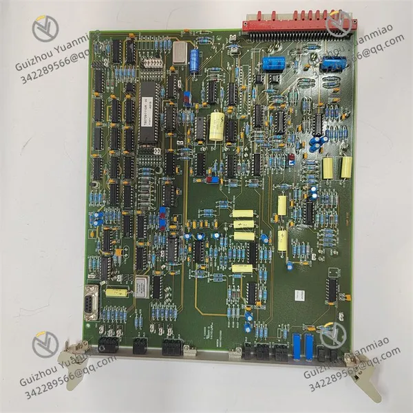
Negotiable MOQ: 1 Piece (Price negotiable depending on order volume and customization)
Key Specifications
Get Latest Price
Material:
Other, Global universal model
Condition:
Other, Global universal model
Task:
Other, Global universal model

Payment & Shipping
Payment Methods:
Port of Shipment:
China
Delivery Detail:
Delivery time depends on order quantity.
Material Other, Global universal model
Condition Other, Global universal model
Task Other, Global universal model
Mathematical Model Other, Global universal model
Signal Other, Global universal model
Customized Non-Customized
Structure Other, Global universal model
Temperature -40℃~+70℃
Dimensions 150mm×100mm×90mm
Humidity 5%~95% RH (non-condensing)
ALSTOM N897163510Q N897163050Q MODEM N897163100U
I. Overview
ALSTOM N897163510Q are new-generation control modules or communication interface units developed by ALSTOM for the rail transit sector, typically applied to train network control systems (TCMS), traction converter control, or on-board equipment condition monitoring. As products of the same series, they are compatible in hardware architecture and can collaboratively achieve data interaction, real-time control, and fault diagnosis functions. The modules are designed in compliance with vehicle-mounted standards such as EN 50155, adapting to wide-temperature (-40℃~+70℃), strong vibration (EN 61373 Class 1A), and electromagnetic interference environments, supporting hot-swapping and redundant configuration to enhance system reliability.

N897163510Q N897163050Q MODEM N897163100U (3)

II. Technical Parameters
Parameter Category N897163510Q Specifications N897163050Q Specifications
Power Input DC 110V±20% (vehicle-mounted standard), typical power consumption: ≤40W no load, ≤80W full load DC 74V±20% (vehicle-mounted standard), typical power consumption: ≤35W no load, ≤70W full load
Communication Interfaces
- 2× MVB (1.5Mbps, supports Master/Slave)
- 2× Ethernet (10/100/1000Mbps, supports EtherCAT)
- 4× RS-485 (Modbus RTU)

- 1× MVB (1.5Mbps, Slave mode)
- 1× Ethernet (10/100Mbps, supports Profinet)
- 2× RS-485 (Modbus RTU)
I/O Channels
- Analog inputs: 8 channels (16-bit accuracy, 0-10V/4-20mA)
- Analog outputs: 6 channels (12-bit accuracy, 0-5V/4-20mA)
- Digital inputs: 16 channels (opto-isolated, 24V DC)
- Digital outputs: 12 channels (relay/transistor hybrid output, max load 2A)

- Analog inputs: 4 channels (16-bit accuracy, 0-10V/4-20mA)
- Analog outputs: 2 channels (12-bit accuracy, 0-5V/4-20mA)
- Digital inputs: 8 channels (opto-isolated, 24V DC)
- Digital outputs: 6 channels (transistor output, max load 1A)
Working Environment
- Temperature: -40℃~+70℃
- Humidity: 5%~95% RH (non-condensing)
- Vibration: EN 61373 Class 1A
- Protection level: IP54

- Temperature: -40℃~+70℃
- Humidity: 5%~95% RH (non-condensing)
- Vibration: EN 61373 Class 1A
- Protection level: IP54
Physical Characteristics DIN rail mounting, dimensions 150mm×100mm×90mm, weight ≤1.5kg, supports hot-swapping DIN rail mounting, dimensions 100mm×100mm×80mm, weight ≤1.0kg, supports hot-swapping

N897163510Q N897163050Q MODEM N897163100U (2)

III. Working PrincipleData Acquisition and Processing Architecture
  • Real-time acquisition of sensor signals (such as traction motor current, bearing temperature, grid voltage) through analog channels, and receipt of switch signals (such as circuit breaker status, driver commands) through digital channels, which are stored in high-speed cache after A/D conversion.

  • Built-in dual-core processor (such as ARM Cortex-A53 + FPGA) enables parallel computing: the CPU handles logical control and protocol parsing, while the FPGA is responsible for high-frequency sampling (up to 50kHz) and real-time filtering to enhance anti-interference capability.

Network Communication and System Collaboration
  • As train network nodes, N897163510Q can serve as an MVB master or slave station to exchange data with the train main control unit (VCU) and converter control unit (DCU); N897163050Q typically acts as a slave station responsible for regional equipment data aggregation.

  • Ethernet interfaces support industrial protocols (such as EtherCAT, Profinet) to enable remote communication with ground monitoring systems, uploading real-time data (such as operating speed, energy consumption) and fault logs.

Control Logic and Closed-loop Regulation
  • Generate output signals through preset algorithms (such as PID control) based on collected data and upper-computer commands (such as traction/braking requests) to drive actuators such as converters and solenoid valves.

  • Support redundant control: when the main module fails, N897163050Q can switch to standby mode to maintain basic control functions (such as emergency braking).

Safety Protection Mechanisms
  • The power supply end integrates EMI filtering and surge protection circuits to suppress vehicle-mounted power fluctuations (such as voltage spikes at startup);

  • Signal channels use opto-isolation (digital quantities) and isolation amplifiers (analog quantities) to reduce electromagnetic interference;

  • Built-in watchdog timer and temperature sensor trigger reset or protective shutdown when program anomalies or chip overheating (>85℃) are detected, and alarm through LED indicators (such as red flashing) and fault codes (such as "E12" for communication timeout).

N897163510Q N897163050Q MODEM N897163100U (1)

IV. Common Faults and Solutions
Fault Phenomenon Possible Causes Solutions
Power indicator off 1. Input voltage out of range
2. Power fuse blown
3. Internal power chip damage
1. Use a multimeter to detect input voltage (confirm 110V for N897163510Q and 74V for N897163050Q)
2. Replace with the same specification fuse (power off required)
3. Contact ALSTOM after-sales to replace the power module
MVB communication interruption 1. Poor grounding of communication cable shield
2. Missing terminal resistor (master mode)
3. Interface chip failure
1. Check if the cable shield is grounded according to EN 50155 standards
2. Install 120Ω terminal resistors at both ends of the MVB network
3. Use an oscilloscope to detect MVB waveforms and replace the interface circuit board if abnormal
Analog input value fluctuation 1. Sensor signal cable not twisted and shielded
2. Abnormal input channel filtering parameters
3. Ground loop interference
1. Re-wire according to standards (signal cables need to be twisted + shielded, away from power cables)
2. Adjust the filtering time constant through configuration software (e.g., increase from 1ms to 5ms)
3. Check if system grounding complies with EN 50121 standards
No digital output response 1. Load current exceeds rated value (N897163050Q max 1A)
2. Output transistor breakdown
3. Control logic error (such as PLC program exception)
1. Use a clamp meter to detect load current and replace with a higher-power drive module if exceeded
2. Disconnect the load, use a multimeter to detect output continuity, and replace the damaged transistor
3. Download the latest firmware and reset control parameters (refer to ALSTOM debugging manual)
Device frequently reports E07 overheating fault 1. Dust blocking the housing cooling holes
2. Ambient temperature exceeds 70℃
3. Poor contact between internal heat sink and chip
1. Clean cooling holes with compressed air (power off required)
2. Add forced air cooling or adjust the installation position
3. Disassemble the module (professional personnel required), reapply thermal grease, and fix the heat sink
Slave station disconnection in N897163510Q master mode 1. Duplicate slave station addresses
2. Mismatched master-slave baud rate
3. Network topology exceeds maximum node count (MVB max 32 nodes)
1. Check slave station addresses through configuration tools (e.g., N897163050Q address must be unique)
2. Ensure both master and slave MVB baud rates are 1.5Mbps
3. Split the network or replace with a higher-capacity MVB gateway
Product Tags: N897163510Q , N897163050Q , MODEM N897163100U

Send Inquiry to This Supplier

* Message
0/5000

Want the best price? Post an RFQ now!
Verified Business License
Business Type
Trading Company
Year Established
2014
Factory Size
1,000-3,000 square meters
Product Certifications
SA8000