Home > Electrical & Electronics > Electrical Control System > Schneider 140CPU42402 Programmable Controller Module

Schneider 140CPU42402 Programmable Controller Module
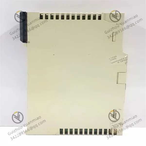
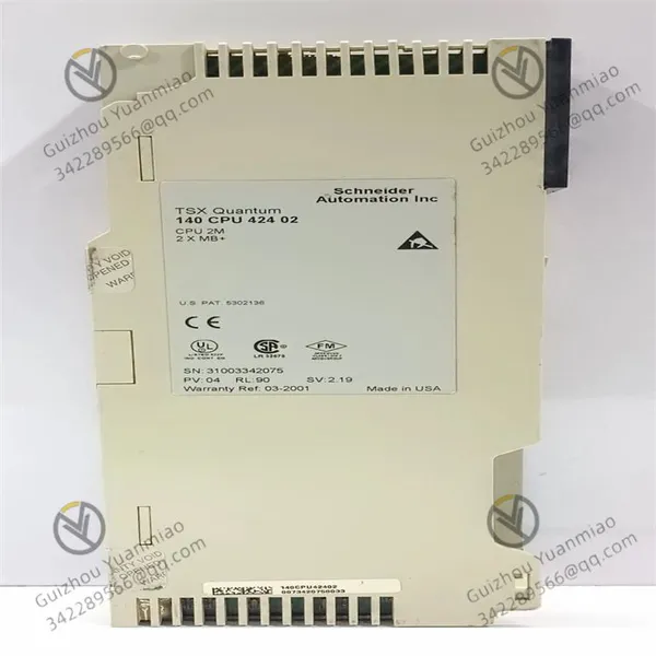
Schneider 140CPU42402 Programmable Controller Module photo-1
Schneider 140CPU42402 Programmable Controller Module photo-2
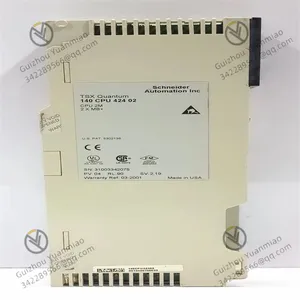
Schneider 140CPU42402 Programmable Controller Module photo-3
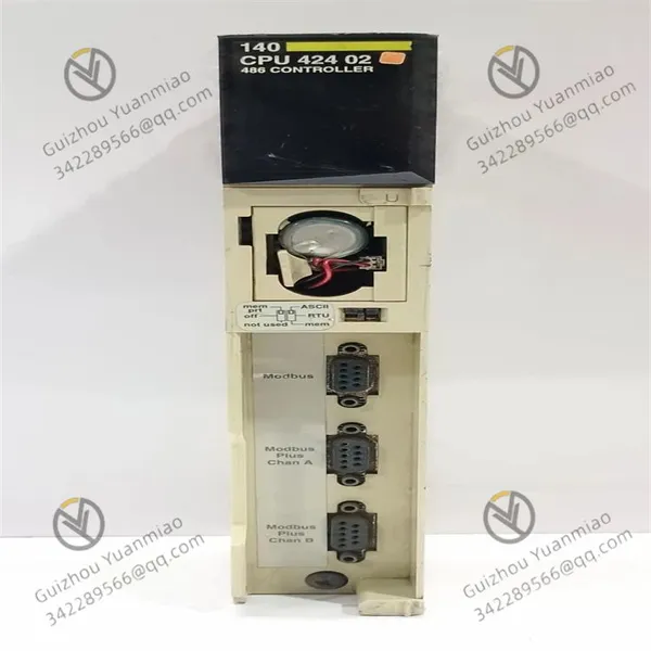
Negotiable MOQ: 1 Piece (Price negotiable depending on order volume and customization)
Key Specifications
Get Latest Price
Material:
Other
Certification:
Other
Function:
Other
Payment & Shipping
Payment Methods:
Port of Shipment:
China
Delivery Detail:
Delivery time depends on order quantity.
Material Other
Certification Other
Function Other
Condition Other
Task Other
Mathematical Model Other
Signal Other
Customized Other
Structure Other

Schneider  140CPU42402  programmable controller module


I. Hardware Architecture and Core ComponentsCentral Processing Unit (CPU)

As the core of the module, it is responsible for executing instructions, processing data, and controlling the operation of the entire system. Its clock frequency and computing power determine the module's processing speed (e.g., the 140CPU42402 may be equipped with a processor of a specific frequency to support efficient logical and arithmetic operations).

Memory System

  • RAM (Random Access Memory): Temporarily stores running programs, data, and intermediate results, supporting fast read/write operations to ensure efficient data access by the processor.

  • Program Memory: Stores user-written control programs (such as PLC programs), typically expandable via memory cards (e.g., PCMCIA cards) to support more complex applications.

  • Data Storage Area: Preserves system configurations, real-time data (e.g., sensor inputs, device status), and historical records.

Communication Interfaces

Integrates multiple communication interfaces (e.g., Modbus, Ethernet, serial ports, etc.), supporting data interaction with external devices (such as sensors, actuators, human-machine interfaces HMI, and other controllers) to achieve distributed control.

Power Supply Module

Connects to industrial power (e.g., 24V DC), supplies power to the CPU and other modules, and features power filtering and voltage stabilization to ensure stable operation in industrial environments.

140CPU42402—02

II. Data Processing and Instruction ExecutionInput Sampling Phase

Collects the status of field devices (e.g., sensor signals, pushbutton switches) through I/O interfaces (requiring matching I/O modules), converts physical signals (e.g., voltage, current) into digital signals, and stores them in input image registers.

Program Execution Phase

Reads instructions one by one from memory according to the user-written control program (based on programming languages such as ladder diagram, ST, SCL, etc.), and performs logical operations, arithmetic operations, or data processing based on the status of input image registers and internal registers.


  • Example: Executes Boolean instructions (AND, OR, NOT) to process switching logic, and performs floating-point operations to process analog data (e.g., temperature and pressure conversion).

Output Refreshing Phase

Writes output signals to output image registers based on program execution results, then converts them into physical signals (e.g., driving relays, solenoid valves) through I/O interfaces to control the actions of field devices.


III. Communication and Network Collaboration MechanismsInternal Communication

Exchanges data in real time with I/O modules and communication modules on the rack via the backplane bus (e.g., the dedicated bus of the Quantum series) to ensure fast response to input/output signals.

External Communication Protocols

Supports industrial communication protocols such as Modbus, Modbus Plus, Ethernet TCP/IP, Profibus, etc., enabling communication with other controllers, host computers (SCADA systems), or cloud platforms:


  • Modbus: Used for serial communication to achieve data collection and control of underlying devices (e.g., instruments, frequency converters).

  • Ethernet: Enables remote monitoring and program downloading, and can be connected to industrial Ethernet for cross-regional centralized management.

Hot Standby and Redundancy Functions (Partial Models)

If the module supports hot standby (e.g., in conjunction with 140CPU67261), the primary and standby processors synchronize data through a dedicated interface. When the primary processor fails, the standby processor automatically takes over to ensure uninterrupted system operation (whether the 140CPU42402 has this function depends on specific model parameters).

140CPU42402—01

IV. Program Operation and Control System LogicCyclic Scanning Mechanism

Adopts a "scanning cycle" working mode, running cyclically in the order of "input sampling → program execution → output refreshing". The length of the scanning cycle depends on program complexity and CPU performance (e.g., Boolean instruction execution time is typically in microseconds to ensure real-time performance).

Interrupt Handling

Supports emergency interrupts (e.g., fault alarms, high-speed counter triggers). When an interrupt signal is received, the current scan is paused, and the interrupt event is processed first to ensure the system's rapid response to unexpected situations.

Fault Diagnosis and Self-Maintenance

Built-in diagnostic functions monitor hardware status (e.g., memory errors, communication failures) and program operation anomalies in real time, and feedback fault information through LED indicators or communication interfaces to facilitate problem troubleshooting by maintenance personnel.


V. Typical Workflow in Industrial Applications

Take an automated production line as an example:


  • Input Collection: Sensors detect material arrival, and signals are input to the CPU's input image area through I/O modules.

  • Logical Processing: The CPU executes the program, judges the material type, calculates the transmission path, and calls the corresponding control logic (e.g., motor start/stop, robotic arm action sequence).

  • Output Control: Drives actuators (e.g., conveyor motors, valves) through the output image area to complete material sorting or processing.

  • Communication Interaction: Uploads production data (e.g., output, failure rate) to the SCADA system via Ethernet, while receiving parameter adjustment instructions from the host computer.

  • 140CPU42402—03

VI. Collaboration with Other Modules

  • With I/O Modules: Connects to digital I/O modules (e.g., 140DDI35300) and analog I/O modules (e.g., 140ACI04000) via the backplane bus to achieve field signal collection and control.

  • With Communication Modules: Accesses industrial networks through Modbus or Ethernet communication modules (e.g., 140NOE77101) to collaborate with third-party devices (e.g., frequency converters, robot controllers).

  • With Power Modules: Relies on dedicated power modules (e.g., 140CPS11420) to supply power, ensuring stable operation of the CPU and peripheral modules.


Conclusion

The working principle of the 140CPU42402 module essentially achieves real-time monitoring and automated control of industrial field devices through "hardware architecture support + program logic control + communication network collaboration". Its core advantages lie in high reliability, real-time performance, and expandability, making it suitable for industrial scenarios requiring precise logical control and complex data processing, such as manufacturing production lines, power monitoring, energy management, etc. In practical applications, control programs need to be written according to specific process requirements, and system integration is achieved through hardware configuration (e.g., rack and I/O module selection).


Product Tags: 140CPU42402

Send Inquiry to This Supplier

* Message
0/5000

Want the best price? Post an RFQ now!
Verified Business License
Business Type
Trading Company
Year Established
2014
Factory Size
1,000-3,000 square meters
Product Certifications
SA8000