








 Contact Platform Support
 Help Center
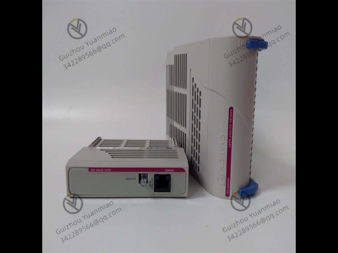
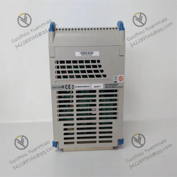
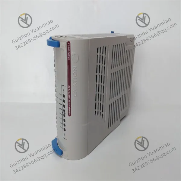
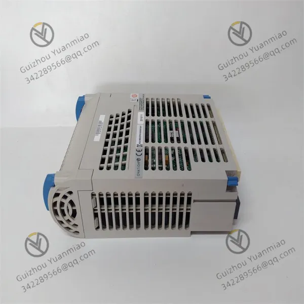
Emerson 5X00300G01 Analog Input Card



Related Products
-
 Emerson 5X00301G01 Digital Output ModuleNegotiableMOQ: 1 Piece
 -
5X00321G01 Emerson Interface ModuleNegotiableMOQ: 1 Piece
-
A6370D Emerson Digital Expansion ModuleNegotiableMOQ: 1 Piece
-
Emerson A6140 Dual-channel Shaft Absolute Vibration MonitorNegotiableMOQ: 1 Piece
-
Emerson 1C31189G03 Speed Detector ModuleNegotiableMOQ: 1 Piece
Emerson 5X00300G01 Analog input card
Function Introduction
Signal conversion: This is the core function of the analog input card. It converts continuously changing analog signals in industrial sites, such as voltage and current signals, into digital signals that can be recognized and processed by computers or other control devices through an internal analog-to-digital converter (ADC).
Signal acquisition: It can collect various analog signals in real time. In industrial production, physical quantities such as temperature, pressure and flow rate can be collected, providing the system with data reflecting the status of the production process, which is convenient for operators or control systems to understand the production situation.
Multi-channel acquisition: It usually has multiple independent analog input channels and can simultaneously collect multiple analog signals. For instance, in large-scale chemical production facilities, temperature and pressure signals from multiple different positions can be collected simultaneously, which enhances the monitoring efficiency and flexibility of the system.
Data transmission: The collected and converted digital signals are transmitted to computers, programmable logic controllers (PLCS), or distributed control systems (DCS), etc. through high-speed data buses. Supports real-time data transmission, can quickly respond to changing analog signals, and provide accurate data feedback for the control system in a timely manner to issue control instructions.
Signal processing and optimization: Some analog input cards are equipped with built-in filters that can filter the input signals, remove high-frequency noise and interference signals, improve signal quality and stability, and thereby enhance the accuracy and reliability of subsequent data processing.
Adapt to different input ranges: It can provide various input range options, allowing for selection based on actual application requirements to ensure that the measured physical quantity is collected and converted within an appropriate range. For example, it can adapt to the signal range output by pressure sensors, temperature sensors, etc. with different measurement ranges.
Working principle
Sensor signal conversion: Firstly, non-electrical physical quantities such as temperature, pressure, and flow in industrial production are converted into corresponding electrical signals (current or voltage) by sensors. For example, a temperature sensor can convert temperature changes into voltage changes, and a pressure sensor can transform pressure values into current signals.
Signal processing: The electrical signal output by the sensor usually does not match the input voltage signal required by the analog-to-digital converter (ADC), so a signal amplification processing circuit is needed. This circuit transforms and amplifies the sensor signal to convert it into a voltage signal that matches the ADC input for subsequent conversion.
Multi-channel signal selection: The 5X00300G01 analog input card typically has multiple analog input channels and is equipped with a multi-channel transfer switch inside. Through the address latch and decoding logic, one of the analog signals can be selected to be sent to the subsequent links for processing. In this way, multiple analog input signals can be collected alternately by A single A/D conversion chip, saving hardware resources.
Sampling hold: The sampling hold device tracks the input analog signal in the sampling state. In the holding state, the instantaneous input analog signal at the end of the previous sampling is maintained until the next sampling state is entered. It is usually composed of analog switches, storage components (capacitors) and operational amplifiers to ensure the stability of the input signal during the A/D conversion process and improve the conversion accuracy.
Analog-to-digital conversion: This is the core link. The A/D converter converts the sampled and held analog input electrical signal into a digital quantity (such as a binary number). The interior of an A/D converter is typically composed of control and timing circuits, successive approximation registers, and conversion circuits, etc. Through specific conversion algorithms, analog signals are quantified into corresponding digital codes.
Digital signal output: The digital quantity after A/D conversion is stored in the three-state output latch buffer. When the output allowable signal is valid, the tri-state gate is opened, and the converted data is output to the computer or control system through the data bus for analysis and processing, and control signals for the production process are issued based on the results.

Send Inquiry to This Supplier


You May Also Like
-
Emerson 1C31166G01 Serial Link ControllerNegotiableMOQ: 1 Piece
-
EMERSON FLOBOSS S600 Traffic ComputerNegotiableMOQ: 1 Piece
-
Emerson A6500-RC API 670 Mechanical Protection Monitor AssemblyNegotiableMOQ: 1 Piece
-
Emerson 1C31179G02 Digital Control System (DCS) ModuleNegotiableMOQ: 1 Piece
-
Emerson 1C31179G01 Remote I/O ModuleNegotiableMOQ: 1 Piece
-
1C31203G01 Emerson Remote Node Controller I/O ModuleNegotiableMOQ: 1 Piece
-
Emerson 1C31204G01 Remote Node I/O ModuleNegotiableMOQ: 1 Piece
-
Emerson 1C31166G02 Digital Input ModuleNegotiableMOQ: 1 Piece
-
Emerson IC695CPE330 CPU Control Unit ModuleNegotiableMOQ: 1 Piece
-
Emerson SP4402 High-performance General-purpose AC Frequency Converter ModuleNegotiableMOQ: 1 Piece


