








 Contact Platform Support
 Help Center
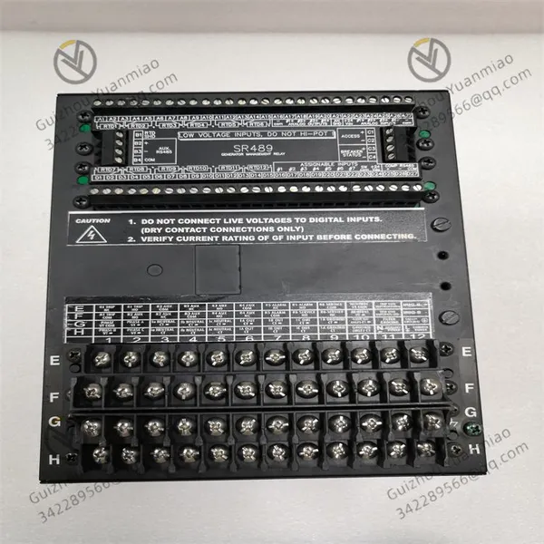
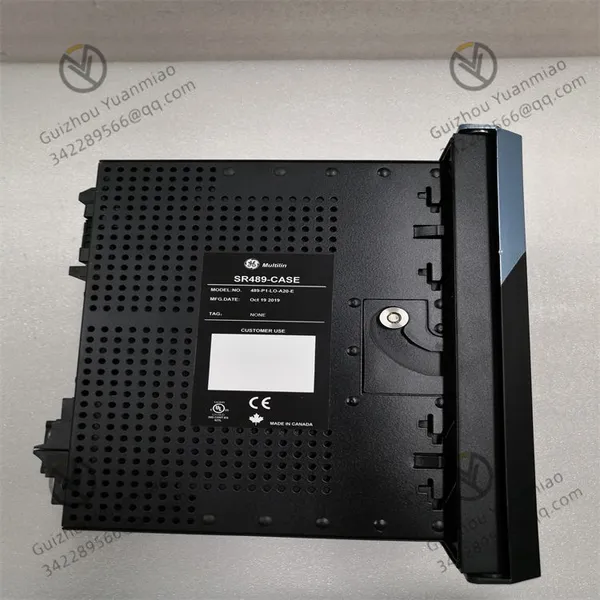
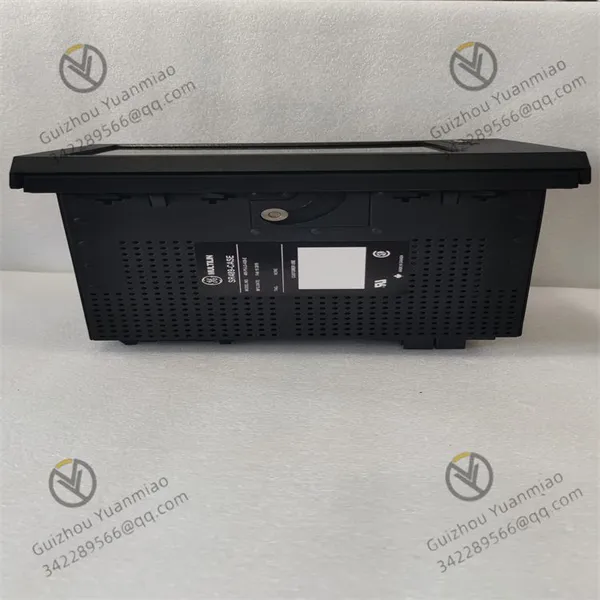
GE 489-P1-HI-A20-T-H Generator Management Relay Module
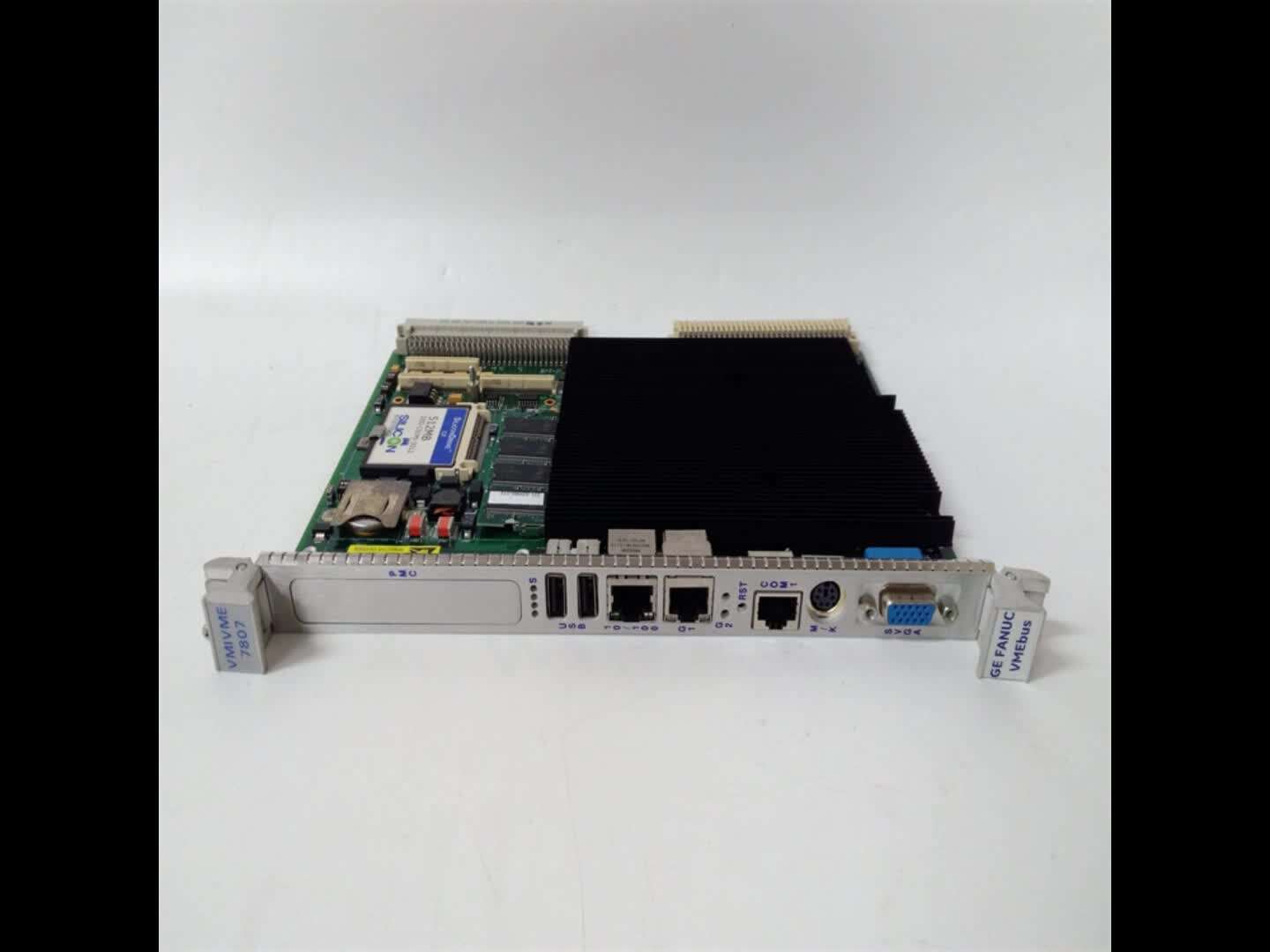
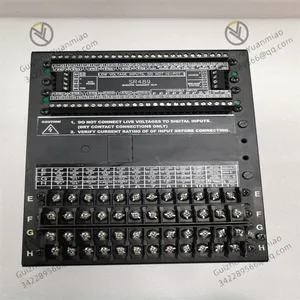
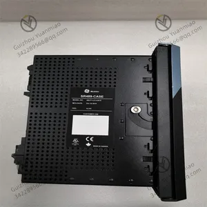
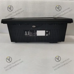



Related Products
-
 GE SR489-P5-LO-A20-E Generator Management Relay ModuleNegotiableMOQ: 1 Piece
 -
GE SR489-P1-LO-A20-T Generator Management RelayNegotiableMOQ: 1 Piece
-
The Basic Unit of GE SR489-P1-LO-A20-E Generator Management RelayNegotiableMOQ: 1 Piece
-
GE UR6CH Digital Input/output ModuleNegotiableMOQ: 1 Piece
-
GE UR6DH Analog Input ModuleNegotiableMOQ: 1 Piece
GE 489-P1-HI-A20-T-H Generator Management Relay Module
I. Core Work Logic Framework
Data acquisition and signal input
Current signal acquisition: Through the secondary input of the 1A phase CT corresponding to "P1", the three-phase currents (IA, IB, IC) of the generator stator winding are monitored in real time, which is used for functions such as differential protection and overcurrent protection.
Voltage and power input: The "HI" type control power supply (90-300VDC/70-265VAC) supplies power to the relay and may also be connected to the system voltage (such as the secondary voltage of the PT) for power direction determination, distance protection, etc.
Auxiliary signal access: Supports external switch quantity input (such as circuit breaker position, start/stop signal), and receives data from other devices through analog quantity input (such as 4-20mA).
2. Signal Processing and Computing
Analog-to-digital Conversion (ADC) : It converts the collected analog quantities (current, voltage) into digital signals, which are processed by the internal microprocessor (MCU).
Algorithm operation: Through the built-in protection logic algorithm (such as the ratio braking characteristic of differential protection, impedance calculation of distance protection, power direction criterion, etc.), the electrical parameters (such as current difference, impedance value, active/reactive power) are calculated in real time and compared with the preset setting values.
Ii. Working Principle of Core Protection Functions
Generator stator differential protection
Principle: Compare the current difference (ΔI) between the inlet and outlet of the generator stator winding. Under normal circumstances, the currents on both sides are balanced (ΔI≈0). When an internal short circuit occurs in the stator winding, a current difference appears on both sides. If it exceeds the set value, a protection action will be triggered.
Algorithm implementation: It adopts the "ratio braking characteristic", that is, it only acts when the differential current exceeds a certain proportion of the braking current, to avoid misoperation in case of faults outside the zone (such as external short circuits).
2. 100% stator grounding protection
Segmented protection logic
Fundamental zero-sequence voltage protection: Monitor the zero-sequence voltage (3U0) of the stator winding to ground. When the stator winding is metallic grounded, 3U0 rises to the set value (such as 15V), and the protection action occurs (covering 85%-95% of stator winding grounding faults).
Third harmonic voltage protection: By comparing the ratio of the third harmonic voltage (3ω) between the neutral point of the stator winding and the machine terminal, when the stator winding is grounded near the neutral point, the change in the distribution of the third harmonic voltage triggers protection (covering the remaining 5%-15% of grounding faults), achieving 100% coverage.
3. Standby phase distance protection
Impedance measurement principle: Calculate the impedance value Z=U/I based on the measured voltage (U) and current (I), and determine the fault location in combination with the power factor. When a short circuit occurs in the system, if the measured impedance is less than the set value (corresponding to the protected section) and the power direction points to the protected area, the protection will act.
Three-stage delay feature: It can be set with stage I (rapid disconnection), stage II (delay), and Stage III (backup), corresponding to different protection zones and fault priorities.
4. Sensitive directional power protection
Power direction determination: By calculating the directions of active power (P) and reactive power (Q), it is determined whether the fault is within the protected area. For example, when there is an external fault of the generator, the power direction flows from the generator to the system. When an internal fault or reverse fault occurs, the power direction reverses, triggering the protection to lock or act.
5. Circuit Breaker Fault Protection (CB Fail)
Logical triggering: When the protection action issues the tripping command, if the circuit breaker does not disconnect within the specified time (judged by the continuous existence of the current), it is determined that the circuit breaker refuses to act, triggering the CB Fail protection and tripping the upper-level circuit breaker to prevent the fault from expanding.
Iii. Principles of Communication and Interaction
Analog output (A20)
The internal calculated electrical parameters (such as current, voltage, and power) are converted into standard analog signals through a 4-20mA current loop and transmitted to the DCS (Distributed Control System) or other equipment to achieve remote monitoring.
2. Display and Communication Interface (T/H characteristics)
Enhanced Display (T) : Through the 10Base-T Ethernet interface, it supports Web interface access or dedicated software (such as Multilin ToolSet) to display information such as electrical parameters, protection status, and fault recording in real time, and supports parameter tuning and fault analysis.
Communication protocol: Compatible with protocols such as Modbus RTU, Modbus TCP/IP, and DNP 3.0, it communicates with the monitoring system via RS232/RS485 or Ethernet to achieve data upload and remote control.
Iv. Support of Hardware Design for Working Principle
Power supply and anti-interference design
The "HI" type wide-range power supply ensures stable operation during voltage fluctuations. The internal power module is equipped with filtering and isolation functions to prevent interference from affecting logical judgments.
The "H" type chemical environmental conformal coating protects the circuit board from corrosive gases and moisture, ensuring the reliable operation of hardware in harsh environments.
2. Drawer-type structure and interface design
The drawer-type structure facilitates the rapid replacement of hardware modules and reduces maintenance time. The input/output interfaces (such as CT/PT terminals, communication ports, and relay contacts) adopt standardized designs and support plug-and-play.
V. Work Process Summary
Real-time monitoring: Current and voltage signals are collected through CT/PT, converted into digital quantities and sent into the microprocessor.
Logical operation: The microprocessor calculates parameters based on preset protection algorithms (such as differential, distance, and power direction) and compares them with the set values.
Protection action: When the parameters exceed the set value, it drives the internal relay contacts to output a trip command and simultaneously records the fault information.
Information interaction: Through analog output, communication interfaces and displays, status data is transmitted to external systems, supporting remote monitoring and fault analysis.

Send Inquiry to This Supplier


You May Also Like
-
GE UR6PH Digital I/O Input/output ModuleNegotiableMOQ: 1 Piece
-
GE UR8NH Digital I/O ModuleNegotiableMOQ: 1 Piece
-
GE UR8LH Universal Relay Series CT/VT ModuleNegotiableMOQ: 1 Piece
-
GE 269PLUS-100P-120 Motor Management RelayNegotiableMOQ: 1 Piece
-
GE 369-HI-R-M-0-E-0-E Motor Management Relay ModuleNegotiableMOQ: 1 Piece
-
GE 469-P5-HI-A20-E SR469 Motor Management Relay Series ModuleNegotiableMOQ: 1 Piece
-
GE 489-P1-H1-A20-T Motor Management Relay Series ModuleNegotiableMOQ: 1 Piece
-
GE 489-P1-HI-A1-E Multi-functional Motor Management RelayNegotiableMOQ: 1 Piece
-
GE 489-P1-HI-A1-T Series Motor Management RelayNegotiableMOQ: 1 Piece
-
GE 489-P1-LO-A1-E Motor Management RelayNegotiableMOQ: 1 Piece


