Home > Electrical & Electronics > Electrical Control System > ABB PFEA112-20 3BSE050091R20 Tension Controller

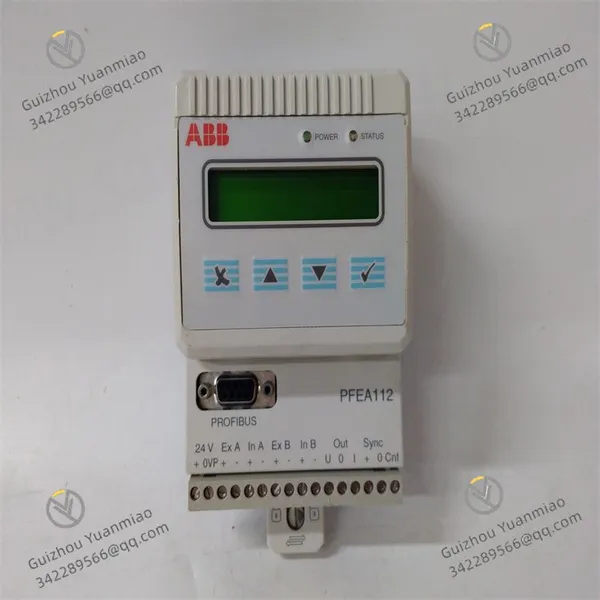
ABB PFEA112-20 3BSE050091R20 Tension Controller

ABB PFEA112-20 3BSE050091R20 Tension Controller photo-1
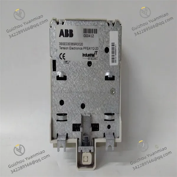
ABB PFEA112-20 3BSE050091R20 Tension Controller photo-2
Negotiable MOQ: 1 Piece (Price negotiable depending on order volume and customization)
Key Specifications
Get Latest Price
Material:
Other, Global universal model
Condition:
Other, Global universal model
Task:
Other, Global universal model

Payment & Shipping
Payment Methods:
Port of Shipment:
China
Delivery Detail:
Delivery time depends on order quantity.
Material Other, Global universal model
Condition Other, Global universal model
Task Other, Global universal model
Mathematical Model Other, Global universal model
Signal Other, Global universal model
Customized Non-Customized
Structure Other, Global universal model
I. Functional Characteristics
  1. High-precision Measurement and Control
  • Equipped with high-precision sensor interfaces, it supports real-time acquisition of material tension signals. Through internal algorithm processing, it achieves precise tension adjustment to ensure stable material tension during production (e.g., in film, cable, and paper manufacturing scenarios).

  • Built-in advanced control algorithms (such as PID control) can quickly adjust outputs based on actual tension feedback, reducing fluctuations and improving product quality.

  • Rich Communication and Interface Configuration
    • Supports multiple communication protocols, including RS232, RS485, and Ethernet, facilitating data interaction with upper-level computers (PLC, HMI) or other control systems for remote monitoring and parameter adjustment.

    • Hardware interfaces include digital input/output (DI/DO), analog input (AI), etc., which can connect peripheral devices such as sensors and actuators (e.g., motor drivers, valves) to adapt to complex industrial scenarios.

  • Flexible Control Modes
    • Manual mode: Directly input control commands via the operation panel or upper-level computer, suitable for debugging or special working conditions.

    • Automatic mode: Automatically adjusts based on preset tension values and real-time feedback without manual intervention, improving production efficiency.

    • Supports manual control, automatic control, and other modes:

  • Industrial-grade Reliability Design
    • Adopts high-quality electronic components with anti-interference capabilities, suitable for harsh industrial environments such as high temperature, humidity, and vibration.

    • Features fault diagnosis and alarm functions (e.g., tension over-limit, sensor failure), supporting real-time monitoring of system status to ensure production safety.

  • User-friendliness and Integration Capability
    • Supports industrial protocols such as OPC and Modbus, enabling seamless integration with other automation devices (e.g., SCADA systems) to build a complete production line.

    • Provides a human-machine interface (HMI) or supporting software for convenient parameter setting, data viewing (such as real-time tension curves and historical records), and multi-language display.

    PFEA112-20 3BSE030369R0020 (2)

    II. Working Principle
    1. Tension Detection and Signal Processing
    • Real-time monitors material tension by connecting tension sensors (such as magnetostrictive or photoelectric types), which convert physical tension into electrical signals (e.g., 4-20mA current, 0-10V voltage).

    • After receiving the electrical signals, the controller processes them through amplification, filtering, linear correction, etc., and converts them into digital signals to ensure data accuracy.

  • Control Calculation and Strategy Execution
    • Compares the actual tension measurement value with the preset target value, calculates the deviation through algorithms such as PID, and generates control quantities (e.g., motor speed, torque adjustment signals).

    • Drives actuators (such as servo motors, tension rollers) to act via output interfaces (analog or digital) to adjust material tension to the target range.

  • Real-time Feedback and Closed-loop Control
    • Continuously monitors the tension status, forming a closed-loop system of "detection - calculation - control - feedback", dynamically optimizing control parameters to ensure tension stability.

    • Supports fault feedback (e.g., triggering alarm output when tension is abnormal) and can linkage other devices to achieve protective shutdown.

    PFEA112-20 3BSE030369R0020 (1)

    III. Control Parameter Setting Steps
    1. Preparations and Equipment Connection
    • Familiarize with materials: Refer to the ABB PFEA112-20 User Manual to clarify parameter ranges (such as tension range, input/output specifications), interface definitions, and safety precautions.

    • Hardware connection: Connect the controller to upper-level computers (such as PC, PLC) or operation panels via interfaces like Ethernet and RS485, ensuring stable communication cables.

    • Power configuration: Access the required power supply (such as 24V DC) and confirm that power parameters match the module's labeling.

  • Enter Parameter Setting Interface
    • Use ABB supporting software (such as DriveWindow, ABB Ability™ system) or the menu function of the operation panel to enter the setting mode through the "Parameter Setting" or "Configuration" entry.

  • Basic Parameter Setting
    • Communication parameters:

      • Select the communication interface (such as RS485), set the baud rate (such as 9600bps), data bits (8 bits), stop bits (1 bit), and parity bit (no parity).

      • Configure the Modbus slave address (such as address 1) or Ethernet IP address to ensure matching with the communication device parameters.

    • Input/output parameters:

      • Analog input: Set the input channel corresponding to the tension sensor (such as AI1), and configure the signal type (4-20mA or 0-10V) and range (such as 0-100N tension).

      • Digital output: Define the trigger condition (tension over-limit) for the alarm output port (such as DO1) and set the output type (relay or transistor)

  • Core Tension Control Parameter Setting
    • Tension measurement parameters:

      • Sensor sensitivity calibration: According to the actual sensor model, input the sensitivity coefficient (such as 0.1N/mV) to ensure that the measured value matches the actual tension.

      • Filter parameters: Set the signal filter time constant (such as 0.5s) to reduce the impact of high-frequency interference on measurement.

    • Target tension and control mode:

      • Input the target tension value (such as 50N), supporting fixed values or dynamic setting via external signals (such as PLC input).

      • Select the control mode: enable PID control in automatic mode, and directly adjust the output percentage (such as 0-100%) in manual mode.

    • PID parameter adjustment:

      • Proportional coefficient (P): Increasing P can speed up the response, but excessive P will cause tension fluctuations. It is recommended to set the initial value to 0.5-1.0 and adjust it according to the debugging effect.

      • Integral time (I): Eliminates static errors. Excessive I will cause response lag. The initial value can be set to 10s and gradually reduced until the error is eliminated.

      • Derivative time (D): Suppresses dynamic overshoot. Excessive D will amplify noise. The initial value is set to 0.1s and adjusted as needed

  • Auxiliary Parameter Setting
    • Alarm parameters:

      • Set the upper/lower tension alarm values (such as target value ±5N) and select the alarm method (acoustic-optical alarm, communication alarm).

      • Configure fault protection actions (such as outputting a shutdown signal when over-limit).

    • Display and storage parameters:

      • Set the display content on the screen (real-time tension, PID parameters, operating status) and adjust the refresh frequency (such as 1s/time).

      • Configure the data storage cycle (such as recording tension data every 10 minutes) and support historical data export

  • Parameter Saving and Debugging
    • After confirming that all parameter settings are correct, execute the "Save" or "Download" operation through the software or panel to make the parameters take effect.

    • No-load debugging: First disconnect the load and observe whether the controller output is normal (such as displaying 0N when there is no tension and signal changes during manual output adjustment).

    • Load test: Access actual materials, gradually increase the tension to the target value, and observe the control effect:

      • If the tension fluctuates greatly, increase P or decrease I; if the response is slow, decrease I or increase D.

      • Record the optimal parameter combination for mass production or save it as a preset recipe

    Product Tags: PFEA112-20 , 3BSE050091R20 , PPD512A10-150000

    Send Inquiry to This Supplier

    * Message
    0/5000

    Want the best price? Post an RFQ now!
    Verified Business License
    Business Type
    Trading Company
    Year Established
    2014
    Factory Size
    1,000-3,000 square meters
    Product Certifications
    SA8000