



Home > Electrical & Electronics > Electrical Control System > ABB PFEA111-65 3BSE050090R65 Tension Controller

ABB PFEA111-65 3BSE050090R65 Tension Controller
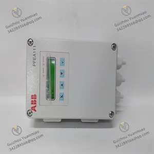
ABB PFEA111-65 3BSE050090R65 Tension Controller photo-1
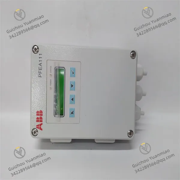
Negotiable MOQ: 1 Piece (Price negotiable depending on order volume and customization)
Key Specifications
Get Latest Price
Material:
Other, Global universal model
Condition:
Other, Global universal model
Task:
Other, Global universal model

Payment & Shipping
Payment Methods:
Port of Shipment:
China
Delivery Detail:
Delivery time depends on order quantity.
Material Other, Global universal model
Condition Other, Global universal model
Task Other, Global universal model
Mathematical Model Other, Global universal model
Signal Other, Global universal model
Customized Non-Customized
Structure Other, Global universal model
Size 180x120x100mm
Transportation weight 3kg
Operating temperature + 5 to + 55°C (32-131°F)

Basic Information


  • Power Supply:

    • System power supply voltage range: 20 to 32Vdc.

    • IP65 main voltage: 24Vdc (18-36Vdc), 100(-15%)-240(+10%)Vac, frequency 45-65Hz, power requirement 7.5W.

  • Dimensions and Weight:

    • Dimensions (hxwxd): 180x120x100mm.

    • Weight: 1.9kg; shipping weight: 3kg.

  • Operating Environment:

    • Operating temperature: +5 to +55°C (32-131°F).

    • Non-operating temperature: -40 to +70°C (-40-158°F).


Functional Characteristics


  • Input/Output:

    • 2 load cell inputs for accurate tension measurement.

    • Voltage and current outputs (A+B) adapt to various actuators for precise tension control.

  • Signal Processing:

    • Adjustable filtering ensures precise signal processing, effectively removing interference to enhance measurement and control accuracy.

  • Display Function:

    • 2×16 character display shows sum, difference, or individual load cell signals for convenient tension monitoring and debugging.

  • Communication:

    • Equipped with RS-485 Modbus-RTU interface for data exchange with other devices, facilitating integration into industrial automation systems.


Application Fields

Mainly applied in industrial scenarios requiring precise tension control, such as papermaking, textiles, printing, and cable manufacturing. It accurately measures and controls material tension during unwinding, rewinding, and processing to ensure product quality.

Product Advantages

  • High control precision: Adopts advanced control technology to ensure material tension stability in processes.

  • Easy installation and maintenance: With IP65 protection, it can be installed in harsh environments and conveniently mounted on DIN rails in electrical cabinets.

PFEA111-65 3BSE050090R65 (2)

Precautions for Installing ABB PFEA111-65 3BSE050090R65 Module


I. Installation Environment Requirements

  • Electrical Safety Environment:

    • Ensure the installation site's electrical system is well-grounded (ground resistance ≤4Ω typically) to avoid lightning or electrostatic interference.

    • Keep the module at least 30cm away from strong electromagnetic interference sources (e.g., inverters, motors, transformers) to prevent signal distortion.

  • Physical Environment Conditions:

    • Operating temperature: -10°C~+55°C (additional cooling/insulation is needed if exceeding the range).

    • Humidity: Relative humidity ≤95% (non-condensing); use a moisture-proof box or ventilation in humid environments.

    • The installation site should be dust-proof and oil-proof; avoid direct contact with dust or liquids (use a protective cover if necessary).


II. Hardware Installation and Wiring Specifications

  • Installation Method and Fixing:

    • The module supports DIN rail or panel mounting; use matching screws to ensure firm installation and prevent poor contact due to vibration.

    • Reserve sufficient space (left/right ≥5cm, up/down ≥10cm) for heat dissipation and maintenance.

  • Wiring Precautions:

    • Power Wiring: Confirm the supply voltage meets the module requirements (typically DC 24V±10%). Connect positive/negative poles correctly, use shielded twisted-pair wires, and series a fuse (rated current ≤5A) in the power loop.

    • Sensor Wiring: Use 4-core shielded cables for load cells. Differentiate input signals (e.g., excitation +/-, signal +/-), avoid cable lengths >100m, and ground the shield at one end (typically on the module side).

    • Output Signal Wiring: Voltage/current outputs (e.g., 0-10V or 4-20mA) must match the input range of actuators (e.g., servo motors, tension controllers). Avoid parallel routing with high-power lines to prevent interference.

    • Communication Interface Wiring: For fieldbuses (e.g., Modbus, CANopen), wire according to protocol standards (e.g., twisted-pair differential signals) and correctly configure terminating resistors (typically 120Ω per bus type).


III. Parameter Configuration and Initialization

  • Pre-power Check:

    • Ensure no short circuits/opens in all wiring, and tighten terminal screws (torque 0.5~0.8N·m) to prevent component damage after power-on.

    • Verify the module model and firmware version (via nameplate or LED indicators) to match the application scenario (e.g., supported bus protocols).

  • Initial Parameter Setting:

    • Sensor Configuration: Set input channels (e.g., Channel 1/2), signal type (mV/V or voltage input), and range (e.g., 0-500kg per sensor specification).

    • Communication Parameters: Configure baud rate, data bits, parity (e.g., Modbus RTU: 9600bps, 8N1) to match the upper computer or other devices.

    • Tension Control Parameters: Use default initial PID parameters (e.g., P=1.0, I=100ms, D=0) and optimize during subsequent debugging.

    • After power-on, initialize parameters via the module panel keys or upper computer software (e.g., ABB Control Builder):


IV. Safety Operations and Protection Measures

  • ESD Protection:

    • Wear an anti-static wrist strap before handling the module. Avoid direct contact with chips or solder joints when touching the circuit board, and store the module in an anti-static bag.

  • Power-off Operation Principle:

    • Cut off the power and wait for capacitor discharge (at least 5 minutes) before any wiring, module plugging/unplugging, or component replacement to prevent electric shock or circuit damage.

  • Protection Class Matching:

    • If installing the module outdoors or in a humid environment, confirm its protection class (e.g., IP20) and use a waterproof box or sealing strip to prevent water intrusion.


V. Debugging and Trial Operation Verification

  • Post-power Preliminary Check:

    • Observe module indicator lights: Power light (PWR) on steady, Run light (RUN) blinking. If the Fault light (ERR) is on steady, power off immediately to check wiring or parameters.

    • View sensor input values via the panel or software. The no-load value should be near zero (allowable ±0.5%FS error); re-calibrate zero if the deviation is too large.

  • Function Test:

    • Manually input simulated tension signals to check linear output changes (e.g., 50% range input corresponds to 50% voltage/current output).

    • Connect actuators for open-loop testing to confirm output signals can drive devices (e.g., motor speed varies with tension signals).

    • Access bus communication to test data transmission/reception (e.g., read module status via the upper computer and check parameter setting responses).

Product Tags: PFEA111-65 , 3BSE050090R65 , 3BSE028140R0020

Send Inquiry to This Supplier

* Message
0/5000

Want the best price? Post an RFQ now!
Verified Business License
Business Type
Trading Company
Year Established
2014
Factory Size
1,000-3,000 square meters
Product Certifications
SA8000

