

Home > Electrical & Electronics > Electrical Control System > ABB UUD148AE01 3BHE014185R0001 Controller Module
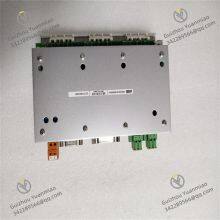
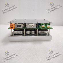
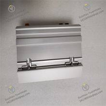
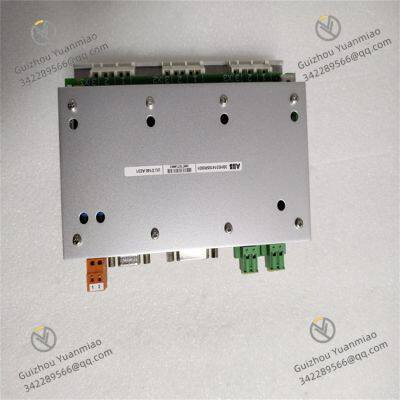
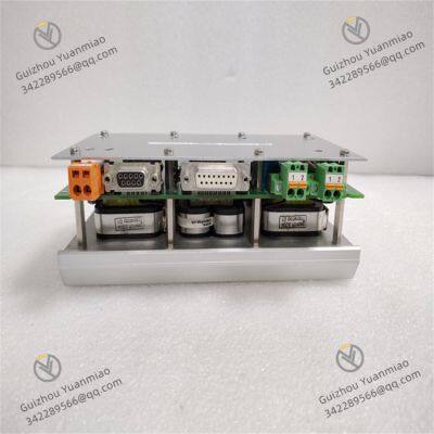
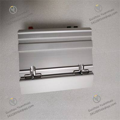
ABB UUD148AE01 3BHE014185R0001 Controller Module
Negotiable
MOQ: 1 Piece (Price negotiable depending on order volume and customization)
Key Specifications
Get Latest Price
Material:
Other, Global universal model
Condition:
Other, Global universal model
Task:
Other, Global universal model
Payment & Shipping
Payment Methods:
Port of Shipment:
China
Delivery Detail:
Delivery time depends on order quantity.
Related Products
-
 ABB 5SHX1445H0001 3BHL000391P0101 IGCT (Integrated Gate Control Transistor) ModuleNegotiableMOQ: 1 Piece
 -
ABB 5SHX06F6004 3BHB003387R0101 Integrated Gate Converter Thyristor (IGCT)NegotiableMOQ: 1 Piece
-
ABB IGCT Module 5SHX08F4502 3BHB003387R0101NegotiableMOQ: 1 Piece
-
ABB IGCT Module 5SHX10H6004 3BHB003230R0101NegotiableMOQ: 1 Piece
-
ABB 5SHX14H4502 Integrated Gate Converter Thyristor (IGCT)NegotiableMOQ: 1 Piece
Material
Other, Global universal model
Condition
Other, Global universal model
Task
Other, Global universal model
Mathematical Model
Other, Global universal model
Signal
Other, Global universal model
Customized
Non-Customized
Structure
Other, Global universal model
Working voltage
DC 24V
Operating temperature
-25°C to +70°C
Power consumption
≤15W
Operating memory
256KB to 1MB RAM
Storage temperature
-40°C to +85°C
Humidity
5% to 95% RH (no condensation)
Weight
Approximately 0.5kg
I. Basic Product Information
II. Technical Parameters

Send Inquiry to This Supplier

* Email
Want the best price?
Post an RFQ now!

1Yr
Business Type
Trading Company
Year Established
2014
Factory Size
1,000-3,000 square meters
Product Certifications
SA8000
You May Also Like
-
ABB 5SHX0660F0002 3BHE022333R0101 IGCT ModuleNegotiableMOQ: 1 Piece
-
ABB IGCT Module 5SHX1060H0003 3BHB020538R0001NegotiableMOQ: 1 Piece
-
ABB IGCT 5SHX1445H0002 3BHL000387P0101 Power ModuleNegotiableMOQ: 1 Piece
-
ABB 5SHX1960L0004 3BHL000390P0104 IGCT ModuleNegotiableMOQ: 1 Piece
-
ABB IGCT Module 5SHX2645L0004 3BHL000389P0104NegotiableMOQ: 1 Piece
-
ABB 5SHX3545L0016 3BHB020720R0002 IGCT ModuleNegotiableMOQ: 1 Piece
-
ABB 5SHY35L4520 5SXE10-0181 Asymmetric Thyristor IGCTNegotiableMOQ: 1 Piece
-
ABB 5SHY3545L0014 3BHE023784R0001 IGCT ModuleNegotiableMOQ: 1 Piece
-
ABB 5SHY3545L0016 3BHB019719R0101 IGCT (Integrated Gate Converter Thyristor) ModuleNegotiableMOQ: 1 Piece
-
ABB PPD513A24-110110 Excitation Control BoardNegotiableMOQ: 1 Piece


