

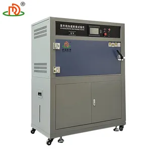
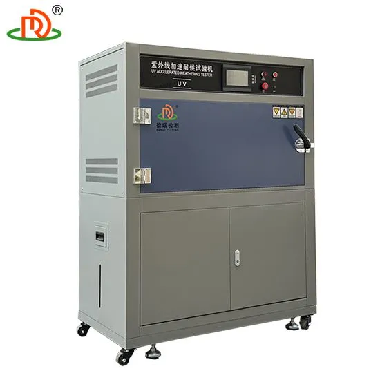
Electronics UV Weathering Test Chamber for PCB Stability
Related Products
-
 ISO 4892-2 Compliant UV Weathering Test MachineUS$ 3500 - 6000MOQ: 1 Set
 -
UV Accelerated Weathering Test Chamber With 0.55 W/m² IrradianceUS$ 3500 - 6000MOQ: 1 Set
-
UVA-340 Lamp UV Weathering Test Machine for Realistic SimulationUS$ 3500 - 6000MOQ: 1 Set
-
High Temperature Yellowing Resistance Testing MachineUS$ 1875 - 3500MOQ: 1 Set
-
300W UV Lamp Yellowing Resistance TesterUS$ 1875 - 3500MOQ: 1 Set
SPECIFICATION
Item |
Specification |
Outside dimension |
1300W×500D×1460Hmm |
Chamber material |
Paint Spray |
Temperature range |
RT~70℃ |
Temperature fluctuation |
±2℃ |
Temperature control |
PID SSR control |
Humidity range: |
≥95%RH |
Controller |
Programmable controller, LCD touch screen |
Control mode |
Balance temperature humidity control (BTHC) |
Test cycle setting |
Exposure, condensation and water spray test cycle is programmable |
Lamp power |
40W/Piece |
Distance from sample to lamp |
50±2mm |
Centre distance between the lamp |
70mm |
Irradiance |
0.45~0.8W/m2 (optional) |
UV lamps |
Imported Atlas UV-A: 315-400nm (8pcs, 1600h lifetime) |
Standard Specimen Size |
75×290mm (24pcs) or 75x150mm (48pcs), max. thickness 5mm |
Testing time |
0~999H, adjustable |
Protection system |
Overload short circuit protection |
Printed Circuit Boards (PCBs) are the backbone of modern electronics, powering everything from medical devices to automotive control systems. However, prolonged exposure to ultraviolet (UV) radiation, humidity, and temperature fluctuations can degrade solder joints, delaminate substrates, and compromise electrical performance. An Electronics UV Weathering Test Chamber for PCB Stability simulates these extreme conditions in a controlled environment, enabling manufacturers to validate long-term reliability and meet stringent industry standards.
Why PCB Stability Testing is Non-Negotiable
A 2023 study by the International Electronics Manufacturing Initiative (iNEMI) found that 22% of field failures in IoT devices stemmed from PCB degradation caused by environmental stress. For mission-critical applications like aerospace or industrial automation, such failures can lead to catastrophic outcomes.
UV weathering testing addresses these risks by accelerating the aging process. For example:
Solder Joint Integrity: UV exposure combined with thermal cycling (e.g., -40°C to 125°C) reveals micro-cracking in lead-free solders.
Substrate Durability: High humidity (up to 98% RH) tests moisture resistance in FR-4 and polyimide materials.
Conformal Coating Performance: Validates UV stability of protective coatings used in outdoor electronics.
Core Innovations in UV Weathering Chambers for PCBs
Modern Electronics UV Weathering Test Chambers integrate precision engineering to replicate real-world stressors:
Full-Spectrum UV Simulation: UVA-340 lamps mimic sunlight’s 295–365 nm range, critical for testing polymer degradation.
Multi-Axis Exposure: Rotating racks ensure uniform UV distribution across irregular PCB geometries.
Dynamic Environmental Controls: Simultaneous adjustments to temperature (±0.5°C accuracy), humidity, and UV intensity.
A breakthrough in 2023 involves AI-powered chambers that predict failure points using machine learning algorithms trained on decades of field data—reducing testing time by 35%.
Industry Applications Driving Demand
Automotive Electronics: EV battery management systems require PCBs to withstand desert UV levels and thermal shock (-40°C to 85°C).
5G Infrastructure: Outdoor base station PCBs undergo 1,000-hour UV tests to ensure 10-year lifespans.
Medical Devices: Implantable electronics are tested for UV-induced oxidation in sterilization environments.
A case study from a German automotive supplier showed a 50% reduction in warranty claims after adopting accelerated UV weathering protocols for dashboard control modules.
Key Standards and Compliance
IPC-9701: Mechanical shock and thermal cycling for surface-mount devices.
JEDEC JESD22-A110: Humidity and temperature bias testing.
IEC 60068-2-5: UV radiation resistance for enclosures.
Choosing the Right Testing Solution
Prioritize equipment with:
Modular Design: Accommodates rigid, flex, and HDI PCBs.
Data Traceability: Cloud-based reporting for audit compliance.
Energy Efficiency: LED UV systems reduce power consumption by 40% vs. traditional lamps.
Step-by-Step Operating Procedure for Electronics UV Weathering Test Chamber in PCB Stability Testing
1. Pre-Test Preparation
Sample Preparation:
Mount PCBs (with solder masks, conformal coatings, or assembled components) onto non-reflective racks.
Label samples for traceability (e.g., batch numbers, test durations).
Chamber Calibration:
Verify UV lamp output (e.g., UVA-340 at 0.76 W/m²/nm) using a radiometer.
Calibrate temperature (±1°C) and humidity (±3% RH) sensors per IEC 60068-3-6 guidelines.
2. Test Parameter Configuration
UV Exposure Cycle:
Set irradiance levels (typically 0.7–1.2 W/m²) to simulate geographic-specific sunlight intensity.
Program alternating UV exposure (8 hours) and condensation (4 hours) phases for accelerated degradation.
Thermal Cycling:
Define temperature ranges (e.g., -20°C to +85°C) to mimic thermal stress in automotive or outdoor electronics.
Adjust ramp rates (e.g., 3°C/min) to avoid thermal shock artifacts.
3. Chamber Loading & Initialization
Sample Placement:
Position PCBs at uniform distances from UV lamps to ensure consistent irradiance.
Avoid shadowing between samples.
Environment Setup:
Fill humidity reservoirs with deionized water to prevent mineral deposits.
Seal the chamber and initiate a pre-test purge to stabilize internal conditions.
4. Test Execution & Real-Time Monitoring
Start Cycle:
Launch the programmed UV/condensation/thermal profile via the touchscreen interface.
Data Logging:
Monitor real-time metrics: UV intensity, chamber temperature, humidity, and elapsed time.
Use integrated sensors to track PCB surface changes (e.g., gloss loss, discoloration).
5. Intermediate Inspections
Scheduled Halts:
Solder mask cracking or delamination.
Copper trace oxidation.
Component warping or solder joint failure.
Pause tests at intervals (e.g., 250, 500 hours) to visually inspect PCBs for:
Document findings with high-resolution imaging or microscopy.
6. Post-Test Analysis
Performance Evaluation:
Measure electrical continuity (e.g., resistance changes) using a multimeter.
Assess adhesion strength of conformal coatings via cross-cut tests per ASTM D3359.
Data Compilation:
Export logged data (CSV/PDF) to compare against baselines or IPC-4101 specifications.
Generate failure analysis reports highlighting UV-induced defects.
7. Chamber Maintenance
Lamp Replacement:
Swap UV lamps after 1,500–2,000 hours to maintain spectral accuracy.
Cleaning Protocol:
Wipe chamber walls with isopropyl alcohol to remove residues.
Clean humidity reservoirs monthly to prevent microbial growth.
8. Compliance Reporting
Standards Alignment:
Validate results against IPC-TM-650 Method 2.6.4 (UV Exposure) and MIL-STD-810G.
Include calibration certificates and test logs for audit readiness.

Send Inquiry to This Supplier


You May Also Like
-
Inner Liner 304 Stainless Steel Yellowing Resistance TesterUS$ 1875 - 3500MOQ: 1 Set
-
Inner Liner 304 Stainless Steel Yellowing Resistance TesterUS$ 1875 - 3500MOQ: 1 Set
-
Textile Yellowing Resistance Testing InstrumentUS$ 1875 - 3500MOQ: 1 Set
-
Ink Yellowing Resistance Test Chamber ManufacturerUS$ 1875 - 3500MOQ: 1 Set
-
Model Parameter Table of Yellowing Resistance Test ChamberUS$ 1875 - 3500MOQ: 1 Set
-
Model Parameter Table of Yellowing Resistance Test ChamberUS$ 1875 - 3500MOQ: 1 Set
-
Wire and Cable Yellowing and Aging Resistance Testing MachineUS$ 1875 - 3500MOQ: 1 Set
-
Solution for Yellowing and Aging Resistance in the Paint IndustryUS$ 1875 - 3500MOQ: 1 Set
-
High Temperature Ventilation Aging Test ChamberUS$ 3250 - 7000MOQ: 1 Set
-
Rotary Ventilation Aging Testing MachineUS$ 3250 - 7000MOQ: 1 Set


