

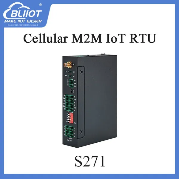
4G IOT RTU S271 4DI/DO 4AI 1TH for Water Plant Data Acquisition

Related Products
-
 ARM Cortex M4 32-bit RISC Core S272 8DI/4DO 6AI/1RS485 32G Memory Applied to LightingUS$ 130 - 178MOQ: 1 Piece
 -
GSM GPRS M2M Internet of Things RTU S272 8DI 6AI 4DO 1TH 1RS485 32G Memory for SubstationsUS$ 130 - 178MOQ: 1 Piece
-
M2M Internet of Things RTU S274 4DI/DO 1TH 32G Memory 1RS485 for Telemetry SystemsUS$ 107 - 154MOQ: 1 Piece
-
Cellular M2M IoT RYU S274 4DI/DO 1TH 1RS485 32G Memory for Lighting MonitoringUS$ 107 - 154MOQ: 1 Piece
-
IoT M2M MODBUS RTU S275 8DI 4DO 6AI 1TH 1RS485 for Lighthouse MonitoringUS$ 107 - 154MOQ: 1 Piece
Wireless Data Acquisition Module 4G IoT RTU S271 is a wireless industrial IoT data monitoring and remote control unit, which is an ideal solution for remote data monitoring, data acquisition, remote control, and real time alarm.
Wireless Data Acquisition Module 4G IoT RTU S271 is a wireless industrial IoT data monitoring and acquisition control SMS alarm, which is an ideal solution for remote data monitoring as well as data acquisition.
S271 |
V |
12bit |
4 |
4 |
0 |
4 |
1 |
X |
200 |
USB |
Item |
Reference Scope |
DC Power supply |
Standard adapter: DC 12V/1.5A Range 9-36VDC |
Power consumption |
Standby:12V/70mA; Working Max.: 12V/300mA |
GSM/3G Frequency |
850/900/1800/1900Mhz/3G (UMTS/HSDPA) |
Transmit power |
Class 4 (2W) at EGSM 900 and EGSM 850 Class 1 (1W) at GSM 1800 and GSM 1900 |
GPRS connectivity |
GPRS multi-slot class 10 |
GPRS Data Transmission |
GPRS data downlink transfer: max. 85.6 kbps GPRS data uplink transfer: max. 42.8 kbps Coding scheme: CS-1, CS-2, CS-3 and CS-4 |
TCP/IP stack |
TCP,UDP |
SIM interface |
Supporting 3V SIM Card |
External antenna |
SMA Antenna interface, 50 Ohm |
Alarm Phone Numbers |
10 telephone numbers for SMS Alert and Dial while alarm. |
Serial Interfaces |
1 USB Port with ±15KV ESD Protection. |
Protocols |
SMS, GPRS UDP,TCP, Modbus TCP |
Digital Inputs |
2/4 Digital inputs, dry contact or wet contact. Logic level: 0~0. 5V or short circuit treated as close, +3~30V or open circuits treated as open. One of the input can be used as counter, sampling frequency is 1Khz; |
Analog Inputs |
2/4 analog inputs, 12bits resolution, supports 0-5V, 0-20mA, 4-20mA output transducers; |
Temp.&Hum Inputs |
AM2301, Range: Temperature: -40°C to +80°C, Humidity: 0~100%RH; |
Relay Outputs |
2/4 Solid Relay outputs, Rated Capacity: 5A/30VDC,5A/250VAC |
Power Outputs |
1 Port, for external device (Transducers or detectors or sensors). |
Memory Capacity |
Internal Memory inside, can save 200 historical events. |
Backup Battery |
3.7V 1200mAH, standby 8-16hours. |
Temperature range |
-10-+70 °C |
I/O Isolation |
Electromagnetic |
Power input/Out |
Over voltage protection and phase-reversal protection |
Humidity range |
Relative humidity 95% (condensation free) |
Exterior dimension |
168mm*113mm*26mm(external Maximum size) |
Net Weight |
1000 g |
LED Indicator Definition | |||
| |||
Power |
RTU status indicator, LED ON when switched RTU on. OFF when switched RTU off. |
||
Alarm |
Alarm Indicator, alarm will ON and flick quickly. Normally is OFF; |
||
Arm |
Arm/Disarmed Indicator, Arm is ON, disarmed is OFF. |
||
Run |
RTU running status indicator, ON or OFF stands for RTU halted, flicks slowly stands for RTU running. |
||
|
GSM/3G module indicator. Flicks quickly(less than 1second per time) stands for searching GSM/3G Network or no SIMCard inside or SIMCard connection is not good or cannot register to GSM/3G network successful. Flicks slowly (about 1sencond per time)stands for GSM/GPRS/3G stands for registered successful and GSM/3G Module standby. |
||
Power Connector Definition | |||
| |||
DC IN+ |
External DC Power input port, Connect to 1.5A@9~36V DC power, positive electrode. |
||
DC IN- |
External DC Power Input port, contact to negative electrode |
||
DC Out+ |
Power source output port, positive electrode. Provides power from RTU to external transducers or sensors or detectors. The output voltage and current is the same as the power from DC IN inputs. |
||
DC Out - |
Power source output port, Negative electrode. |
||
DIP Switch Definition | |||
| |||
For S270, 2 and 3 switches are useless. | |||
SET/RUN |
For setting the RTU Mode is in Configuration Mode or Run mode. Switch it to upside is Set Mode, under this mode, the user can use PC Configurator via USB cable to configure the RTU Parameters or Read Parameter settings. Switch it to Downside is Run Mode, under this mode, the RTU is in Running mode. |
||
0/V/mA |
The 1st channel of analog input type switch. If not use this channel then no matter is upside or downside. Switch it to upside stands for the 1st analog input should connect to 0~5V voltage output transducer. Switch it to Downside stands for the 1st analog input should connect to 0~20mA or 4~20mA current output transducer. |
||
1/V/mA~3/V/mA |
The 2nd ~4th channel of analog input type switch. If not use this channel then no matter is upside or downside. Switch it to upside stands for the related analog input should connect to 0~5V voltage output transducer. Switch it to Downside stands for the related analog input should connect to 0~20mA or 4~20mA current output transducer. |
||
Analog Input Definition | |||
| |||
|
Analog inputs, 12bits resolution, supports 0-5V, 0-20mA, 4-20mA output transducers, please refer to abovementioned DIP Switch Definition to connect the correct transducers. For S270, 2+/2- and 3+/3- ports are useless. | |||
0+/0- |
The 1st Channel Analog input. + stands for positive electrode, - stands for negative electrode. |
||
1+/1- ~ 3+/3- |
The 2nd ~4th Channel Analog input. + stands for positive electrode, - stands for negative electrode. |
||
Digital Input Definition | |||
| |||
|
Dry contact or wet contact. Logic level: 0~0. 5V or short circuit treated as close, +3~30V or open circuits treated as open. One of the input can be used as counter, sampling frequency is 1Khz. For S270, 2/3 and GND ports are useless. | |||
0 |
The 1st digital input, positive electrode. |
||
1~3 |
The 2nd ~ 4th digital input, positive electrode. |
||
GND |
GND for digital inputs, negative electrode. |
||
ATN Port Connector Definition | |||
ATN |
GSM/3G Antenna connector, 50Ohm, SMA female. |
||
USB Port Connector Definition | |||
USB |
USB port, for configuration and upgrading firmware and exporting historical data; |
||
Temperature&Humidity Sensor Port Definitions | |||
| |||
T/H |
Temperature & Humidity sensor AM2301 inputs. Measurement Range: Temperature: -40°C to +80°C, Humidity: 0~100%RH. |
||
Digital Solid Relay Output Connector Definition | |||
| |||
|
Solid Relay inside for outputs, Rated Capacity: 5A/30VDC,5A/250VAC. For S270, 2+/2- and /3+/3- ports are useless. | |||
0+/0- |
The 1st Channel Solid Relay Output. + stands for positive electrode, - stands for negative electrode. |
||
1+/1- ~ 3+/3- |
The 2nd ~ 4th Channel Solid Relay Output. + stands for positive electrode, - stands for negative electrode. |
||

Send Inquiry to This Supplier


You May Also Like
-
Cellular IoT Modbus RTU S275 8DI 4DO 6AI 1RS485 1TH for Bank ATM Anti-Theft MonitoringUS$ 107 - 154MOQ: 1 Piece
-
Cellular IoT Modbus RTU S275 8DI 4DO 6AI 1RS485 1TH for Bank ATM Anti-Theft MonitoringUS$ 107 - 154MOQ: 1 Piece
-
GSM/3G/4G IoT M2M RTU S475 8DI 6AI/PT100 4Relay for Smart CitiesUS$ 159 - 238MOQ: 1 Piece
-
GSM/3G/4G IoT M2M RTU S475 8DI 6AI/PT100 4Relay Suitable for Collecting Electrical DataUS$ 159 - 238MOQ: 1 Piece
-
GSM/3G/4G IoT M2M RTU S475 8DI 6AI/PT100 2RS485 for Weather MonitoringUS$ 159 - 238MOQ: 1 Piece
-
Cellular IoT M2M RTU Ethernet S475E 8DI 6AI/PT100 2RS485 8G Memory for Camera MmonitoringUS$ 163 - 219MOQ: 1 Piece
-
Cellular IoT M2M RTU Ethernet S475E 8DI 6AI/PT100 2RS485 8G Memory for Camera MmonitoringUS$ 163 - 219MOQ: 1 Piece
-
4G SMS Remote Terminal Unit S475 for Fire Panel MonitoringUS$ 159 - 238MOQ: 1 Piece
-
GSM 3G M2M RTU S270 Series ARM Cortex 32 Bit Core 2DI/DO 2AI for Energy ManagementUS$ 89 - 149MOQ: 1 Piece
-
BLIIOT S270 Cellular IoT RTU 2DI 2DO 2AI 1TH for Barrier Lighting SolutionsUS$ 89 - 149MOQ: 1 Piece


