








 Contact Platform Support
 Help Center
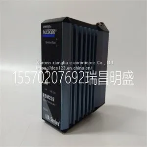
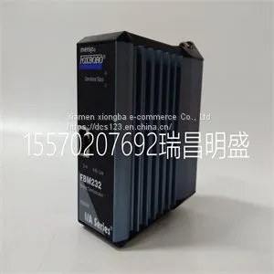
Module Spare Parts FBM232 P0926GW



Related Products
-
 Module Spare Parts FBM233 P0926GXUS$ 1 - 100000MOQ: 1 Piece
 -
Module Spare Parts FCP270 P0917YZUS$ 1 - 100000MOQ: 1 Piece
-
Module Spare Parts A4H254-8F8T P0973JPUS$ 1 - 100000MOQ: 1 Piece
-
Module Spare Parts ACU-01B 3HNA024871-00102US$ 1 - 100000MOQ: 1 Piece
-
Module Spare Parts FBM212 P0914XLUS$ 1 - 100000MOQ: 1 Piece
Focus on DCS, PLC, robot control system and large servo system.
Main products: various modules / cards, controllers, touch screens, servo drivers.
Advantages: supply of imported original products, professional production parts,
Fast delivery, accurate delivery time,
The main brands include ABB Bailey, Ge / fuanc, Foxboro, Invensys Triconex, Bently, A-B Rockwell, Emerson, ovation, Motorola, xyvom, Honeywell, Rexroth, KUKA, Ni, Deif, Yokogawa, Woodward, Ryan, Schneider, Yaskawa, Moog, prosoft and other brands
| FBM232 P0926GW |
Use the following procedure to install a new switch to an existing stack configuration. 1. Ensure that power is off on the new switch being installed. 2. Use one of the following methods to complete the stack cable connections: – If the running stack uses a daisy chain topology, make the stack cable connections from the bottom of the stack to the new switch (that is, STACK DOWN connector from the bottom switch of the running stack to the STACK UP connector on the new switch). – If the running stack uses a ring stack topology, break the ring and make the stack cable connections to the new switch to close the ring. 3. Apply power to the new switch. Connecting AC Power To connect a switch to the AC power source, refer to Figure 1‐3 on page 1‐3 and proceed as follows: 1. Plug the power cord into the switch AC power connector. 2. Plug the other end of the power cord into a dedicated grounded AC outlet (not shown). The type of power outlet and power cord are country‐dependent. 3. Observe the power CPU LED (not shown), located on the front panel. During the initialization, the CPU LED will start by illuminating solid amber, then start blinking green, then blinking amber, then blinking green again until the end of the initialization, and then turns solid green. Note: This procedure assumes that the new switch being added has a clean configuration from manufacturing and is running the same firmware image version as other switches in the stack. Important Considerations About Using Clear Config in a Stack When using the clear config command (as described in the Enterasys A4 CLI Reference Guide) to clear configuration parameters in a stack, it is important to remember the following: • Use clear config to clear config parameters without clearing stack switch IDs. This command WILL NOT clear stack parameters and avoids the process of re-numbering the stack. • Use clear config all when it is necessary to clear all config parameters, including stack switch IDs and switch priority values. Note: The power supply in the switch has automatic voltage sensing that allows connection to power sources ranging from 100 to 240 VAC. Note: If you plan to connect all the switches quickly to allow automatic Manager selection, wait until all switches are fully operational before proceeding to the next step. If you plan to power up each switch and allow it to become fully operational before applying power to the next switch, proceed to the next step. Note: If the CPU LED illuminates solid red, there was a critical failure. For more information about the LED indications and troubleshooting, refer to Chapter 3, Troubleshooting. If you need additional help, contact Enterasys Networks. Refer to “Getting Help” on page xvii for details.

Send Inquiry to This Supplier


You May Also Like
-
Module Spare Parts FBM215 P0917TQUS$ 1 - 100000MOQ: 1 Piece
-
Module Spare Parts FBM216B P0927AJUS$ 1 - 100000MOQ: 1 Piece
-
Module Spare Parts FBM219 P0916RHUS$ 1 - 100000MOQ: 1 Piece
-
Module Spare Parts FBM223 P0917HDUS$ 1 - 100000MOQ: 1 Piece
-
Module Spare Parts FBM230 P0926GUUS$ 1 - 100000MOQ: 1 Piece
-
Module Spare Parts FC-TSAI-1620MUS$ 1 - 100000MOQ: 1 Piece
-
Module Spare Parts FI820F 3BDH000031R1US$ 1 - 100000MOQ: 1 Piece
-
Module Spare Parts FI830F 3BDH000032R1US$ 1 - 100000MOQ: 1 Piece
-
Module Spare Parts FLN3524AUS$ 1 - 100000MOQ: 1 Piece
-
Module Spare Parts FLN4234AUS$ 1 - 100000MOQ: 1 Piece


