

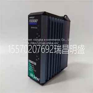
Module Spare Parts FBM230 P0926GU

Related Products
-
 Module Spare Parts FBM232 P0926GWUS$ 1 - 100000MOQ: 1 Piece
 -
Module Spare Parts FBM233 P0926GXUS$ 1 - 100000MOQ: 1 Piece
-
Module Spare Parts FCP270 P0917YZUS$ 1 - 100000MOQ: 1 Piece
-
Module Spare Parts A4H254-8F8T P0973JPUS$ 1 - 100000MOQ: 1 Piece
-
Module Spare Parts ACU-01B 3HNA024871-00102US$ 1 - 100000MOQ: 1 Piece
Focus on DCS, PLC, robot control system and large servo system.
Main products: various modules / cards, controllers, touch screens, servo drivers.
Advantages: supply of imported original products, professional production parts,
Fast delivery, accurate delivery time,
The main brands include ABB Bailey, Ge / fuanc, Foxboro, Invensys Triconex, Bently, A-B Rockwell, Emerson, ovation, Motorola, xyvom, Honeywell, Rexroth, KUKA, Ni, Deif, Yokogawa, Woodward, Ryan, Schneider, Yaskawa, Moog, prosoft and other brands
| FBM230 P0926GU |
Stack Manager Selection When you install and connect all the high‐speed stacking cables to the switches in the stack, the following occurs once power is applied to the switches: • The switch that will manage (manager) the stack is automatically established with all other switches established as member switches in the stack. When the switches complete their initialization, one of the switches in the stack will illuminate its MGR LED, indicating that it is the stack manager. The MGR LED on each member switch will be off. • The hierarchy of the switches that will function as backup manager is also determined in case the current manager malfunctions, is powered down, or is disconnected from the stack. • The Console port on each member switch is deactivated. Only the Console port on the manager switch is active for out‐of band configuration to set the IP address, password, and other configuration settings. Once you know which switch is the manager, proceed to “Connecting to the Console Port for Local Management” on page 2‐20. Recommended Procedures for New and Existing Stacks Installing a New Stackable System of Up to Eight Switches Use the following procedure to install a new stack of up to eight switches out of the box. Before applying power, make all physical connections with the stack cables as described in “Connecting Stacking Cables” on page 2‐5. 1. Once all of the stack cables have been connected, individually power on each switch from top to bottom (connecting power to a switch is described in “Connecting AC Power” on page 2‐9). If the switches are powered on almost simultaneously, the system will automatically select the first one that powers up as the Master switch and the others as member switches. The switches are assigned unit IDs in the order that they become fully operational. You can control the unit ID assignment according to the physical position in a stack. When you power up each switch and allow it to become fully operational before applying power to the next switch, the first one becomes the manager and all the next switches will join that stack (regardless of priority, firmware revision, or MAC address). The switches are assigned unit IDs in the order that you power on each switch. 2. Connect to the Console port of the manager switch. 3. (Optional) If desired, change the management switch using the set switch movemanagement command as described in the Enterasys A4 CLI Reference Guide. 4. Once the desired master switch has been selected, reset the system using the reset command as described in the Enterasys A4 CLI Reference Guide. Important The following procedures assume that all switches have a clean configuration from manufacturing. When adding a new switch to an already running stack, it is also assumed that the new switch is using the same firmware image version as other switches in the stackactivated. This enables you to set the IP address and system password using a single Console port. Now each switch can be configured locally using only the manager’s Console port, or in‐band using a remote device and the CLI set of commands described in this section. For procedures used for various types of connections to the Console port, refer to “Connecting to the Console Port for Local Management” on page 2‐20. Once a stack is created (more than one switch is interconnected), the following occurs: 1. Switch (unit) IDs are arbitrarily assigned on a first‐come, first‐served basis. 2. Switch IDs are saved against each module. Then, every time a switch is power‐cycled, it will initialize with the same switch ID. This is important for port‐specific information (for example: fe.4.12 is the 12th Fast Ethernet port on switch number 4). 3. The management election process uses the following precedence to assign a manager switch: a. Previously assigned/elected manager switch b. Management assigned priority (values 1–15) c. Hardware preference level d. Highest MAC Address Note: You can stack an A4H model switch only with other A4H model switches. You cannot stack an A4H model switch with switches that are not A4H model switches. That is, A4 switches do NOT stack with A2 switches.

Send Inquiry to This Supplier


You May Also Like
-
Module Spare Parts FBM212 P0914XLUS$ 1 - 100000MOQ: 1 Piece
-
Module Spare Parts FBM215 P0917TQUS$ 1 - 100000MOQ: 1 Piece
-
Module Spare Parts FBM216B P0927AJUS$ 1 - 100000MOQ: 1 Piece
-
Module Spare Parts FBM219 P0916RHUS$ 1 - 100000MOQ: 1 Piece
-
Module Spare Parts FBM223 P0917HDUS$ 1 - 100000MOQ: 1 Piece
-
Module Spare Parts FC-TSAI-1620MUS$ 1 - 100000MOQ: 1 Piece
-
Module Spare Parts FI820F 3BDH000031R1US$ 1 - 100000MOQ: 1 Piece
-
Module Spare Parts FI830F 3BDH000032R1US$ 1 - 100000MOQ: 1 Piece
-
Module Spare Parts FLN3524AUS$ 1 - 100000MOQ: 1 Piece
-
Module Spare Parts FLN4234AUS$ 1 - 100000MOQ: 1 Piece


