








 Contact Platform Support
 Help Center
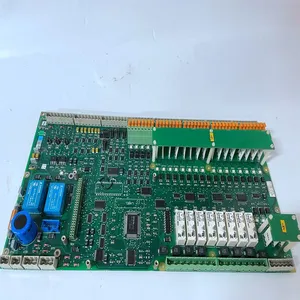
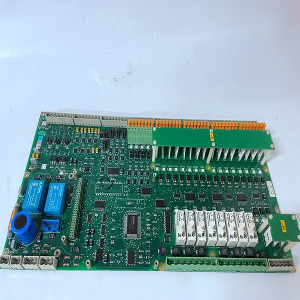
3ASC25H209 DATX110


Related Products
Brand:ABB
Type:3ASC25H209 DATX110
Origin: the Swiss
Warranty: 365 days
Colour: new/used
Shipping method: Courier delivery
Module of PLC, DCS, ESD system card, the card is a vibration monitoring system, steam turbine control system module, the advantages of the gas generator spare parts brand: Allen Bradley, BentlyNevada, ABB, Emerson Ovation, Honeywell DCS, Rockwell ICS Triplex, FOXBORO, Schneider PLC, GE Fanuc, Motorola, HIMA, TRICONEX, Prosoft etc. Various kinds of imported industrial parts
Our main products are widely used in metallurgy, petroleum, glass, aluminum manufacturing, petrochemical industry, coal mine, papermaking, printing, textile printing and dyeing, mechanical, electronic manufacturing, automobile manufacturing, plastic machinery, electric power, water conservancy, water treatment/environmental protection, boiler heating, energy, power transmission and distribution and so on.
A 24 V power supply is available within the 505E to power external transducers or devices. This supply has two breaker protected output channels. One power supply channel (VA1) is capable of providing 24 Vdc ±10%, @ 200 mA maximum output current, to power 505E current inputs and auxiliary devices. Power connections can be made through terminals 55, 59, 63, 70, and 74 with terminal 78 as the common. Refer to Figure 2-7. WARNING The total current draw through terminals 55, 59, 63, 70, and 74 cannot exceed 200 mA or the 505E’s internal power supply breaker (CB1) will open resulting in a possible CPU reset and trip condition. All load must be removed from the specified terminals to allow the breaker to reset. The second power supply channel is capable of providing 24 Vdc ±10%, @ 200 mA maximum output current, to power 505E current outputs and auxiliary devices. Power connections can be made through terminals 85, 88, 91, 97, 100, and 103 with terminal 78 as the common. Refer to Figure 2-7. WARNING The total current draw through terminals 85, 88, 91, 97, 100 and 103 cannot exceed 200 mA or the 505E’s internal power output breaker (CB2) will open resulting in a possible CPU reset and trip condition. All load must be removed from the specified terminals to allow the breaker to reset.
Shields and Grounding An individual shield termination is provided at the terminal block for each of the speed sensor inputs, actuator outputs, analog inputs, analog outputs, and communications ports. All of these inputs should be wired using shielded, twisted-pair wiring. The shields should be connected to earth ground at all intermediate terminal blocks, as well as terminated at the control terminal block. The exposed wire length, beyond the shield, should be limited to one inch. Relay outputs, contact inputs, and power supply wiring do not normally require shielding, but can be shielded if desired. For EMI reasons, it is recommend that all low-current wire (terminals 52 through 121) be separated from all high-current wire (terminals 1 through 51). Input Power ground terminal #3 should also be wired to external ground. Refer to Figure 2-7. Figure 2-9. Shielded Wire Connections Speed Sensor Inputs To sense speed, the control accepts signals from one or two passive magnetic pickup units (MPUs) or active proximity probes mounted off of a gear which is connected or coupled to the turbine’s rotor. Because of the differences between passive MPUs, active proximity probes, and the sensing circuits required for each type, jumpers are provided to allow field configuration of each speed input depending on the type of probe used. See Table 2-1 for jumper options, and Figure 2-4 for jumper locations.
 Verification of jumper location is recommended before system startup or operation. A passive MPU provides a frequency output signal corresponding to turbine speed by sensing the movement of a gear’s teeth past the MPU’s pole piece. The closer the MPU’s pole piece is to a gear’s teeth and the faster the gear turns the higher a passive MPU’s output amplitude will be. The 505E must sense an MPU voltage of 1 to 25 Vrms for proper operation. With proper MPU, gear size, and MPU-to-gear clearance, speed measurement should be capable down to 100 Hz. Standard MPU clearance is recommended to be .010” to .040” from tooth face to pole piece. For information on selecting the correct MPU or gear size please refer to Woodward manual 82510. See Figure 2-7 for wiring schematic.

Send Inquiry to This Supplier


You May Also Like
-
PP845 3BSE042235R1US$ 1043 - 2263MOQ: 1 Piece
-
3BSE008538R1US$ 1044 - 2264MOQ: 1 Piece
-
81943A041-1US$ 1044 - 2264MOQ: 1 Piece
-
DSSR122 4899001-NKUS$ 1044 - 2264MOQ: 1 Piece
-
LXN1604-6US$ 1045 - 2265MOQ: 1 Piece
-
PFSK151 3BSE018876R1US$ 1045 - 2265MOQ: 1 Piece
-
TP867 3BSE043664R1US$ 1045 - 2265MOQ: 1 Piece
-
PM865K01 3BSE031151R1US$ 1047 - 2267MOQ: 1 Piece
-
3BHL000986P0006US$ 1047 - 2267MOQ: 1 Piece
-
5SHY3545L0010 3BHB013088R0001 3BHE009681R0101 GVC750BE101US$ 1047 - 2267MOQ: 1 Piece


