

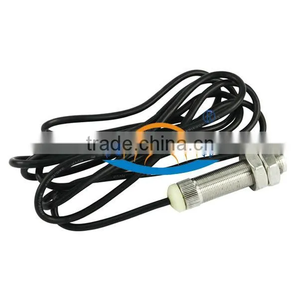
YD69 CW/CCW Measurement Speed Sensor


Related Products
-
 YD69 CW/CCW Dual-channel SensorUS$ 100.00 - 140.00MOQ: 1 Piece
 -
YD62 Magnetic Speed SensorUS$ 90.00 - 110.00MOQ: 1 Piece
-
YD240 Rotation Speed TransmitterNegotiableMOQ: 1 Piece
-
Vibration Measuring Instrument Vibration Measurement Tool Accelerometer Monitor YD240 Rotation Speed TransmitterUS$ 99 - 299MOQ: 1 Set
-
YD62 Gear Tooth Speed SensorUS$ 49 - 109MOQ: 1 Piece
Hall Dual-channel speed sensor has good low and high frequency characteristics. The low frequency is as low as 0Hz, can be used for zero-speed measurement of rotating machinery, because the sensor can provide a certain phase of two speed signals, so you can judge for CW or CCW; high frequency is as high as 20KHz, can meet the high-speed measurement requirements of vast majority of industrial field.
A. Hall Dual-Channel Sensor Overview
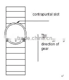
Hall Dual-Channel Sensor is installed on the shell of the measured machine, inducting the raised part or concave slots of the magnetizer, it shows the corresponding level, it is used to detect axis of rotation speed, linear velocity. The method to get the acceleration of the measured machine is by calculation processing. The sensor has good low and high frequency characteristics. The low frequency is as low as 0Hz, can be used for zero-speed measurement of rotating machinery, because the sensor can provide a certain phase of two speed signals, so you can judge for CW or CCW; high frequency is as high as 20KHz, can meet the high-speed measurement requirements of vast majority of industrial field. It is contactless measurement between the sensor and the measured gear, no wearing and easy installation. The output waveform is square wave that duty cycle for about 50%.
Hall Dual-Channel Sensor has the features of great adaptability, wide speed range, wide temperature range and strong vibration resistance.
B. Hall Dual-Channel Sensor Technical Parameters
(The parameters of phase difference is the data when the speed gear modulus is 2, in line with DIN867 standard.)
1. Installation
The measured machine need to be a magnetizer with raised parts or concave slots.
Suggestion: modulus ≥1.7, the material need to be magnetic low-carbon steel.
P.S.: If the width of the raised part or concave slots is different from the width of the flat surface, the waveform width will be affected.
Installation gap: 0.3-1 .5 mm, typical value is 1.0mm.
P.S.: Depends on the vibration of measured machine.
2. Output Characteristics
Frequency response characteristics: 0 ~ 20 kHz
Output channels: Double channel
Output waveform: square wave, rise and fall by time 12 u s + 40%
Output amplitude:
high level: U b-(1.8 V + 40%); low level: < 2.2 V
Pulse duty cycle: 50%±25%
Phase difference: 90±30°
P.S.: Depends on the Installation and the rotation direction of rotating parts. This parameter is suitable for the installation on the figure 4 of the manual.
Load capacity: ±20mA (Maximum)
Output impedance: <47Ω
3. Work environment requirements
Working power supply: U b=15VDC±30% (8V~28V)
Current consumption: ≤35mA
Working temperature: -40℃~125℃ (head)
Vibration resistance performance: vibration (10Hz ~ 2KHz) 30g, shock 100g
Sealing:IP6813.
4. Electrical characteristics
Power source polarity protection: yes
Output short circuit protection: yes
Insulating strength: 1000V 50Hz,1min ( channel and shell)
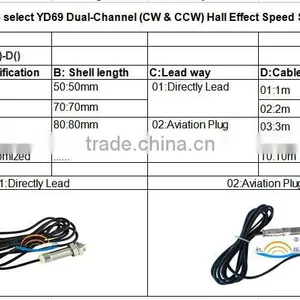
5. External cable and connection
The wire attached: 6 × 0.5mm2 shielded cable, standard length is 1.0 meter (can be extended according to user’s requirements)
C. working Principle
1. Speed measurement principle
When the speed gear rotates, the sensor will provide a frequency f(Hz)= n×m/60 (n is the rotating speed, p is the gear teeth) of the square wave signal, It can be used for the locomotive electronic control system to do sampling detection of locomotive speed and diesel engine speed.
The inductor need to be a magnetizer, can be groove, raised screw or toothed gear.
There are several parameters as follow for using the sensor to do detection:
m -numbers of the inductors on the measured rotating magnetizer.
n -speed
f -input signal frequency
s -the set meter factor (depends on characteristics of the speed measuring instruments, some speed measuring instruments set gear teeth directly, please follow the manual of the speed measuring instrument you selected to set meter factor)
S=60/M
After setting the induction numbers of measurement system, the setting coefficient of the instrument can be made sure. According to the sensors in each channel that corresponding induction numbers to determine the coefficient of each channel.
For example, as to the speed measurement of a rotation axis, there are 30 gear teeth on the axis, it means the teeth numbers of induction Z = 30, then the output frequency of each channel f = (30/60)´n, rotating speed n = 2f, that means the measured frequency multiply 2 is equal to actual speed. Set the coefficient of speed measuring instrument in 2, means s = 2, then the actual speed of rotor can be displayed directly. Similarly, if every rotor produce 2 signals, then set the coefficient s = 30. Others can be deduced by analogy.
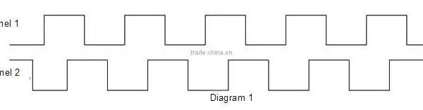
2. CW/CCW discrimination measuring principle
Hall Dual-Channel sensor can discriminate CW run and CCW run easily.
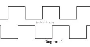
According to the application example in specification 4 to install it, when it runs CW as figure 4, the output wave of channel 1 is ahead of channel 2 90°. Waveform diagram is as follow:
When the direction of rotation is opposite to figure 4, the waveform of channel 2 is ahead of channel 1 90°. Waveform diagram is as follow:
From the above chart, we can do phase discrimination for the waveforms of channel 1 and channel 2, then to do reverse discrimination.
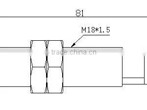
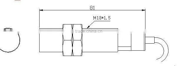
D. Dimensions and installation diagram
The follow diagram is the dimensions and installation diagram for Hall Dual-Channel Sensor.
Rz is the radius of gear, X is the distance from addendum to the surface of sensor (0.3≤X≤1.5).
Application Example:
One tachometer wheel with 60 gear teeth, mode number is 2, if the sensor is installed as figure 4, channel 1 is ahead of channel 2 and the phase difference is about 90 °.
If the mode number is not 2, push the sensor to some angle r when installing the sensor, you can also get the phase difference as about 90 °, shown as figure 5.
For more details, please call us, there are professionals will offer you to the professional solution for your specific conditions.
E. Installation, Usage and Fault handling
1. About SJ series Hall Dual-Channel Sensor, it is not allowed the working power supply connect with locomotive battery, it should connect with isolated power supply to output.
2. The sensor output wire must be connected with no mistake according to the specification, make sure there is no short circuit and open circuit appears. Strictly prohibit pulse output and power supply to be short circuit.
3. Install the sensor according to the instructions in the installation diagram. After adjust the gap between the gear and head of sensor to 0.6mm, tighten it.
4. Before the sensor installed into the shell of measured machine, use a ferromagnetic contacts and leaves the sensor, if the output current changes, it is normal.
5. In normal condition, if the output current no changes, the sensor is damaged.
6. If the wire is damaged by external force, the solution is to change a sensor.
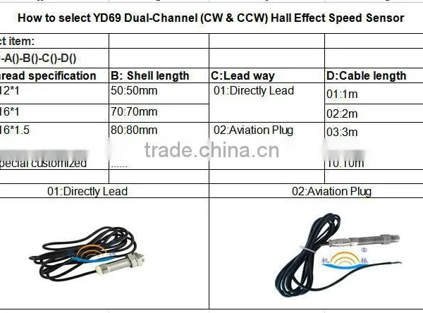
F. Ordering Information
1. Please clearly indicate the model of sensor, the length of external wiring and the connecting form.
2. If you have special requirements, please communicate with us.
3. The actual dimension can be customized by your special needs.
4. One specification for one batch order as a rule.

Send Inquiry to This Supplier

You May Also Like
-
SICK ICR845-2E1020 SICK Industrial Barcode Scanner for Logistics & AutomationNegotiableMOQ: 1 Piece
-
ISX15 QSX15 Diesel Engine Pressure Temperature Sensor 4921475NegotiableMOQ: 1 Ampere
-
Pressure SensorNegotiableMOQ: 2000 Pieces
-
Sick WL4S-3F2132V Order Number: 1046428 Product Family: W4S-3 Inox Product Family: Photoelectric SensorsUS$ 100 - 200MOQ: 1 Piece
-
20428461 20732304 20428462 Heavy Duty Truck Sensor Parts Fuel Tank Level Sensor For VOLVONegotiableMOQ: 1
-
King Pigeon Temperature Humidity Transducer THI100 Temperature Humidity Detector Wireless SensorUS$ 2 - 31MOQ: 5 Pieces
-
Ultrasonic Position Liquid Level Position SensorUS$ 200 - 700MOQ: 1 Piece
-
Crank Oil Seal for Toyota Auto Parts Oem 90311-95012US$ 1 - 10MOQ: 1 Piece
-
SHT10 Humidity & Temperature SensorUS$ 1 - 2MOQ: 5 Pieces
-
Wholesales & Retails HCA131A High Performance Dual Axes Tilt Sensor Switch Led Light With Tilt Switch From Shenzhen FactoryNegotiableMOQ: 1 Piece


