








 Contact Platform Support
 Help Center
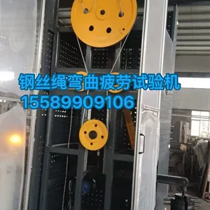
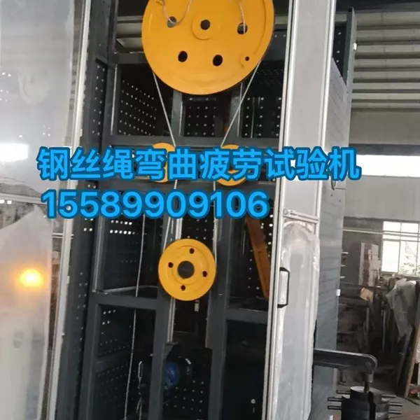
Steel Wire Rope Flexing Fatigue Tester,Steel Wire Rope Combined Bending and Tensile Fatigue / Steel Wire Rope Bending-tension Fatigue Test
Product Spotlights


Related Products
-
 Electronic Universal Testing MachineCNY 10000 - 50000MOQ: 1 Piece
 -
Electronic Universal Testing MachineUS$ 4000 - 5000MOQ: 1 Piece
-
Packaging Material Testing MachineUS$ 4000 - 5000MOQ: 1 Piece
-
Customized Horizontal Tensile Testing MachineUS$ 80000 - 100000MOQ: 1 Piece
-
Cup Extrusion Test MachineUS$ 9988 - 10000MOQ: 1 Bag
GB/T 12347-2025 — Specimen Preparation Specifications and Dimensional Requirements
Chapter 7 of the standard systematically stipulates the specimen requirements for three categories of tests, reflecting the full-process quality control from material sampling to preparation.
7.1 Steel Wire Rope Bending Fatigue Specimens
Specimens shall be taken from finished rope reels or coils, avoiding the fused end portions. Cutting methods such as abrasive wheel cutting, pressure cutting, or shear cutting are recommended. After cutting, the wire ends shall be bound with mild steel wire to prevent unlaying. The specimen shall remain straight and free from initial bending or damage. These requirements ensure the representativeness and comparability of test results.
7.2 Steel Wire Rope (Sling) Axial Tensile Fatigue Specimens
For the end terminations of steel wire rope specimens, socketing by casting or swaging is recommended, as these processes can form a reliable force transmission path. For complete steel wire rope sling specimens, Annex A of the standard provides schematic diagrams of six common termination forms, including swaged socket, cast socket, spliced eye, clamped termination, wedge socket, and combined termination types.
The specimen length requirements vary significantly according to rope type and diameter (see Table 3). For example, for multi-strand steel wire ropes with diameter d ≤ 6 mm, the specimen length shall be not less than 300 mm, while for single-strand ropes of the same diameter, the requirement is not less than 500 mm.
7.3 Steel Wire Rope Sling Combined Tension-Bending Fatigue Specimens
The specimen length L shall be not less than 3500 mm. This relatively long dimension ensures a sufficient transition zone in the bending section, preventing end effects from influencing the test results. Particular attention shall be paid to the symmetry and coaxiality of the termination structures at both ends during specimen preparation, which is a prerequisite for the accurate application of combined tension-bending loads.
1. Main Frame System
The main frame is primarily composed of the cylinder base, cylinder-piston assembly, fixed crosshead, and load cell. The cylinder base, steel plate welded frame, and fixed crosshead form the loading frame. The piston is connected to the tensile grips, and the fixed crosshead is equipped with tensile fixtures (pin-type) to connect both ends of the specimen. The single-rod double-acting low-friction piston cylinder drives the movable crosshead under hydraulic pressure, thereby applying the test force to the specimen. The fixed crosshead is connected to the loading frame via pin connections, with the test space adjusted by piston control.
2. Hydraulic Power Unit
The hydraulic power unit consists of four major components: the oil pump-motor assembly, the tank (including valve block and auxiliary equipment), the piping system, and the main power system. Detailed technical specifications are provided in Section 2 — Hydraulic Power Unit Technical Description.
3. Control, Measurement, and Display System
The loading of test force is controlled by a proportional servo valve dedicated to hydraulic testing machines, ensuring convenient operation.
Microcomputer-based control technology is employed for test force load holding.
The test force is measured by a load cell.
The computer screen displays various test data and plots curves such as force vs. time, with automatic curve data processing.
Complete file operation and data storage functions are provided; test data are output in ASCII format to facilitate secondary data processing by users.
Test reports can be printed via printer.
Comprehensive safety protection devices are incorporated:
Overload protection: When the test force exceeds 2% to 5% of the maximum force of the selected range, the system unloads automatically.
Stroke protection: When the piston displacement reaches the forward or rearward limit position, the oil pump motor shuts down.
Safety guard: The protective cover ensures operator safety in the event of specimen rupture.
Additional safeguards include oil temperature monitoring, oil level monitoring, and oil-resistant protection devices to ensure system safety.
4. Basic Specifications
| Parameter | Specification |
|---|---|
| Maximum Force | 500 kN to 2000 kN (50 t to 200 t) |
| Specimen Diameter Range | Φ32 mm to Φ60 mm |
| Test Frequency | 0.5 to 2 Hz (frequency reduction for large tonnage to maintain accuracy; arbitration ≤ 5 Hz per GB/T 38814) |
| Accuracy Class | Class 2 or higher (per GB/T 25917.1), indication error ±1% |
| Loading Mode | Electro-hydraulic servo control (closed-loop force control, sinusoidal/triangular waveform) |
| Cycle Counting | Preset cycle count with automatic stop |
| Stress Ratio (R) | R = 0.2 to 0.4 |
| Alignment | Automatic alignment device, eccentric load ≤ 5% |
| Applicable Standards | GB/T 38814, GB/T 33364, ISO 4309 |

Send Inquiry to This Supplier

You May Also Like
-
Manhole Cover Pressure Test MachineNegotiableMOQ: 1 Bag
-
Manhole Cover PressUS$ 9988 - 19888MOQ: 1 Bag
-
Electronic Universal Testing MachineUS$ 9988 - 19888MOQ: 1 Bag
-
Metal Bellows Testing MachineUS$ 1 - 9988MOQ: 1 Bag
-
Fatigue Testing Machine,Fatigue Test,Material Life TestingUS$ 9988 - 19988MOQ: 1 Piece
-
Ceramic Membrane Support Compressive and Flexural Testing MachineUS$ 9988 - 19988MOQ: 9988 Bags
-
Safety Belt Static Load Tester, Safety Helmet Impact Test, Elevated Work Equipment Strength Test for Power SystemsUS$ 9988 - 19888MOQ: 1 Piece
-
Spring Testing Machine,Disc Spring Testing MachineUS$ 9988MOQ: 1 Bag
-
Dental Material Testing Machine,Adhesive Bond TesterUS$ 9988MOQ: 1 Case
-
Máy Thử Nén StatUS$ 9988MOQ: 1 Pack


