








 Contact Platform Support
 Help Center
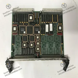
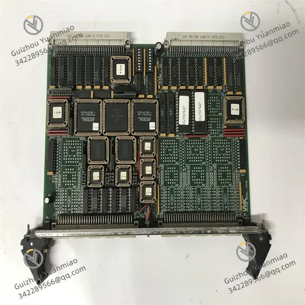
GE VMIVME-1150 64-channel Optically Isolated Digital Input Board



Related Products
-
 GE DS200SHVMG1AGE High Voltage M-Frame Interface BoardNegotiableMOQ: 1 Piece
 -
GE T35E00HAHF8FH6AM8HP6EUXXWXX Control ModuleNegotiableMOQ: 1 Piece
-
GE DS200TCPDG2BEC Power Distribution BoardNegotiableMOQ: 1 Piece
-
GE IS230SNRTH2A Resistance Temperature Detector Input BoardNegotiableMOQ: 1 Piece
-
GE 531X307LTBAFG1 LAN I/O Terminal BoardNegotiableMOQ: 1 Piece
The GE VMIVME-1150 is a 64-channel optically isolated digital input board based on the VME bus architecture. It is specially designed for industrial control, data acquisition and high-reliability embedded systems. Its core function is to convert discrete switching signals from on-site high-voltage / high-interference environments into VME-bus readable digital signals through optocoupler isolation, realizing electrical isolation and noise suppression to ensure system stability.
1. Product Positioning and Functions
Signal Acquisition and IsolationCollects on-site 5–48VDC digital signals (such as valve limit, emergency stop button, relay contact, proximity switch status). All 64 channels adopt full optocoupler isolation with isolation withstand voltage of 1000V continuous / 7500V impulse, completely eliminating ground loop and common-mode interference.
Flexible ConfigurationSupports input polarity (positive / negative logic), optional signal filtering and channel grouping configuration. Eight 8-bit ports support independent addressing and are compatible with 8-bit / 16-bit VME data transmission, adapting to read/write modes of different controllers.
Status Monitoring and DiagnosisReports channel input status in real time and supports contact closure detection. Cooperates with the VME bus to implement I/O access permission management (non-privileged / supervisor mode), facilitating system fault location and maintenance.
High-Reliability IntegrationAdopts standard Double Eurocard form factor, compatible with VMEbus backplane. Redundant design with dual 64-pin DIN connectors simplifies field wiring and system expansion.
2. Technical Features and Specifications
2.1 Hardware Architecture
Bus Interface: Standard VMEbus (A16/A24/A32 addressing), supports 8/16-bit data transmission.
Channel Configuration: 64 independent optically isolated inputs, divided into 8 groups × 8 bits; each group can be independently enabled and configured.
Electrical Isolation: Optocoupler isolation; 1000VAC continuous withstand voltage, 7500VAC impulse withstand voltage; isolation between channels and between channels and ground.
2.2 Key Parameters
Input Voltage: 5–48VDC (compatible with voltage source / current sinking input).
Operating Environment: Operating temperature: 0–55℃; storage temperature: -40–85℃; relative humidity: 20%–80% (non-condensing).
Power Consumption: +5VDC; typical 1.1A, maximum 2.2A.
Physical Dimension: Double-height VME board (approx. 233×160mm), standard rack mounting.
3. Application Scenarios
Industrial Automation: Discrete signal acquisition for DCS/PLC systems, production line equipment status monitoring, safety interlock signal input.
Power & Energy: Auxiliary equipment status monitoring in power plants, high-voltage switch position acquisition, isolation of relay protection contact signals.
Rail Transit: Signal acquisition for vehicle-mounted control systems and track equipment status monitoring, reliable operation under strong electromagnetic interference.
Test & Measurement / Military Industry: Discrete signal acquisition for embedded measurement and control systems, status monitoring of military electronic equipment, meeting high isolation and anti-vibration requirements.
4. Product Advantages
Strong Isolation and Anti-Interference: Optocoupler isolation plus high-withstand-voltage design completely isolates on-site high voltage and noise, suitable for harsh industrial environments.
Flexible Compatibility: Wide voltage input, multi-logic polarity, 8/16-bit bus adaptation; compatible with mainstream VME controllers and operating systems.
High Reliability and Long Service Life: Industrial-grade components, redundant connectors and wide-temperature design support 7×24-hour continuous operation and reduce maintenance costs.
5. Precautions
Overvoltage input (>48VDC) is strictly prohibited; otherwise, the optocouplers and board circuit will be damaged.
Ensure VME backplane slots are clean and in good contact during installation to avoid loose connections caused by vibration.
Distinguish positive / negative logic during field wiring and confirm input signal type before configuration to prevent logic errors.
Maintain good cabinet heat dissipation during board operation; ambient temperature exceeding 55℃ will degrade stability and service life.
Do not hot-swap the board when powered on. Cut off system power and discharge before operation to prevent static damage to electronic components。

Send Inquiry to This Supplier


You May Also Like
-
GE IS200EGDMH1ADF Exciter Gate Driver ModuleNegotiableMOQ: 1 Piece
-
GE F650NFLF2G5HIP6E Relay Protection EquipmentNegotiableMOQ: 1 Piece
-
GE IC695CRU320CA-EL Redundant Control UnitNegotiableMOQ: 1 Piece
-
GE VMIVME-2170A Optically Coupled Digital Output BoardNegotiableMOQ: 1 Piece
-
GE MIVII1000E00HI00 Communications ModuleNegotiableMOQ: 1 Piece
-
GE DS3800XTFP1E1C Thyristor Fan-Out BoardNegotiableMOQ: 1 Piece
-
GE 760-P1-G1-S1-LO-A20-R 760 Feeder Management RelayNegotiableMOQ: 1 Piece
-
GE DS200SDCIG2AEB Power Supply and Instrumentation BoardNegotiableMOQ: 1 Piece
-
GE IC693DSM302-AE Motion Mate Digital Servo ModuleNegotiableMOQ: 1 Piece
-
GE DS200SHVMG1AFE SCR High Voltage Interface BoardNegotiableMOQ: 1 Piece


