








 Contact Platform Support
 Help Center
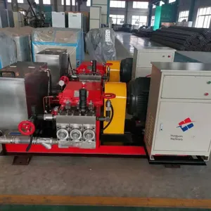
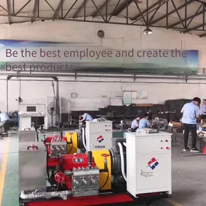
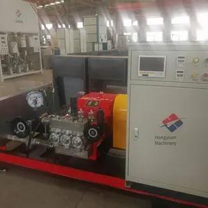
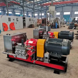
High-pressure and Large-flow Pressure Test Pump, Cnc Pressure Tester, Hose Assembly Pressure Testing Machine


Related Products
-
 High - Quality Fire Extinguisher Annual Inspection and Maintenance, Fire - Fighting Equipment for Shopping Malls, Wide Application Range and Good QualityUS$ 4923.08MOQ: 1 Unit
 -
Low Investment, Quick Return. for Fire Extinguisher Maintenance and Annual Inspection Equipment, Trust Hongyuan Machinery.US$ 4923.08MOQ: 1 Unit
-
Supply of Complete Sets of Equipment, Fire Extinguisher Annual Inspection Equipment, Complete Sets of Maintenance Products for Dry Powder, Carbon Dioxide and Water-type Fire ExtinguishersUS$ 4923.08MOQ: 1 Unit
-
Annual Inspection, Inflation, Powder Filling, Testing of Fire Extinguishers, Maintenance of Fire - Fighting Equipment, Fire - Fighting Technical ServicesUS$ 4923.08MOQ: 1 Unit
-
Annual Inspection of Fire Extinguishers, Maintenance, Upkeep and Testing of Fire-fighting Equipment, Dry Powder, Carbon Dioxide, Water-basedUS$ 4923.08MOQ: 1 Unit
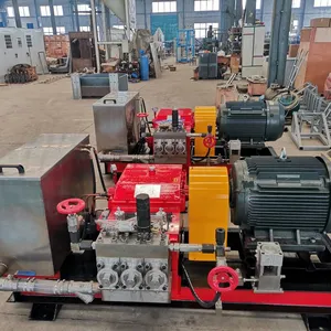
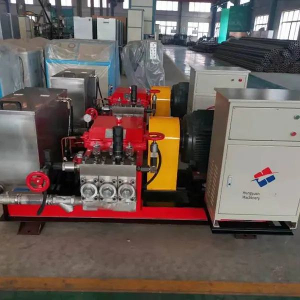
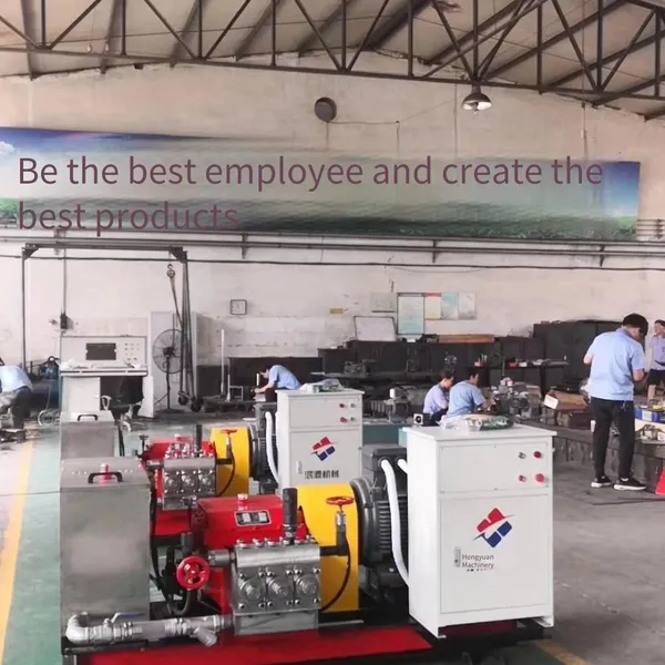
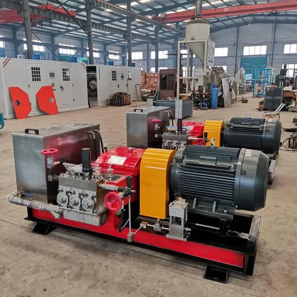
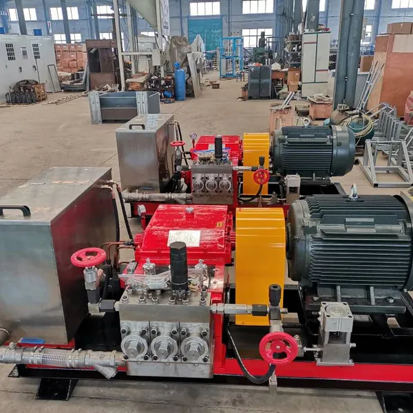
Raoyang Hongyuan Machinery Co., Ltd. has improved and extended the design of the 3DSY - S70 series electric pressure test pumps based on high - pressure and large - flow pressure test pumps. These pumps not only feature a compact structure, safety and reliability, large flow, high efficiency, and a wide high - pressure coverage range, but also have a wide range of applications, strong compatibility, simple operation, and convenient mobility. The machine can use a motor or a diesel engine as the power source, making it suitable for operations indoors, outdoors, or in the wild where there is no power supply. The performance and quality of this product are implemented in accordance with JB/T9089 - 1999 "Pressure Test Pumps" or JB/T6909 - 93 "Ultra - High - Pressure Pumps".
High - Pressure and Large - Flow Pressure Test Pumps, CNC Pressure Test Machines, Hose Assembly Test Pressure Machines Uses
This machine can be used in all places where pressure burst tests and strength tests are required for various pressure vessels, boilers, pipelines, valves, etc., for burst and pressure tests; it can also be used for oilfield wellheads for water injection. The test pressure can be increased from normal pressure to the rated discharge pressure. When equipped with a microcomputer control system, fully automated remote operation can be achieved. The medium used in this machine is generally clean water at normal temperature, and emulsions, anti - rust water, and neutral oils with a viscosity similar to that of water can also be used.
Technical Parameters of High - Pressure and Large - Flow Pressure Test Pumps, CNC Pressure Test Machines, Hose Assembly Test Pressure Machines
Model |
3D - SY 7500/22 |
3D - SY 6000/28 |
3D - SY 4500/35 |
3D - SY 3300/50 |
3D - SY 2300/70 |
3D - SY 1800/90 |
3D - SY 1500/110 |
3D - SY 1200/140 |
|
Rated Pressure (MPa) |
22 |
28 |
35 |
50 |
70 |
90 |
110 |
140 |
|
Nominal flow rate (L/h) |
7500 |
6000 |
4500 |
3300 |
2300 |
1800 |
1500 |
1200 |
|
Plunger diameter (mm) |
Ф45 |
Ф40 |
Ф35 |
Ф30 |
Ф25 |
Ф22 |
Ф20 |
Ф18 |
|
Plunger stroke (mm) |
70 |
||||||||
Reciprocating times (min-1) |
375 |
||||||||
Motor speed (rpm) |
1480 |
||||||||
Motor power (KW) |
55 |
Main components and working principle of high-pressure large-flow pressure test pump, numerical control pressure tester, and hose assembly test press
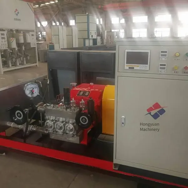
This product consists of a high-pressure reciprocating pump, a throttle pressure regulating valve, a safety valve, a check valve, a manual high-pressure unloading valve, a high-pressure hose, an electric control box, etc.
The working principle of this machine is that the motor drives the high-pressure reciprocating pump through a coupling. Normal-temperature clean water enters the reciprocating pump through the water inlet pipe. After passing through the water inlet and outlet valves, the throttle pressure regulating valve, and the check valve, high-pressure water is formed and transported to the device under test via the high-pressure hose.
1. High-pressure reciprocating pump: This is a horizontal three-plunger pump, divided into a power end and a hydraulic end.
(1) Power end: It is composed of the machine body (including the frame, crankshaft, connecting rod, piston, gear pair, oil pump, etc., as shown in the schematic diagram of the power end structure in Figure 1) and the coupling. The motor is directly connected to the pinion shaft. Two pairs of herringbone helical gears perform first - stage deceleration. The crank - link mechanism converts the rotary motion into the reciprocating linear motion of the crosshead. The pinion shaft drives the oil pump to suck and press oil. The engine oil is forced to lubricate the crankshaft bearing, piston pin, etc. through the oil filter.
(2) Hydraulic end: It consists of the pump body, the high - pressure cylinder (including the high - pressure cylinder body, water inlet valve, water outlet valve, plunger pair, etc., as shown in the schematic diagram of the hydraulic end structure in Figure 2), and the safety valve. The high - pressure cylinder body is fixed on the frame. The crosshead drives the plunger to reciprocate in the high - pressure cylinder body, causing the working volume in the cylinder to change periodically. When the plunger is in the suction stroke, the volume in the cylinder increases, the water outlet valve closes, creating a partial vacuum. The working medium enters the cylinder through the water inlet valve under atmospheric pressure. Conversely, the water inlet valve closes, and the working medium enters the pump body connected to the high - pressure cylinder through the water outlet valve, and then is transported to the throttle pressure regulating valve and the check valve, and reaches the device under test through the high - pressure hose. High - pressure water is formed due to the resistance of the device under test.
A safety valve is installed on the pump body, which is used for over - pressure protection of the system. The opening pressure of the safety valve has been set at the factory. Users are not allowed to adjust it arbitrarily, and it cannot be used as a relief valve.
2. Throttle pressure regulating valve (schematic diagram of the throttle pressure regulating valve structure in Figure 3): An accessory for adjusting the working pressure of the system. (Models 1500/110 and 1200/140 do not have this accessory.) This valve has two functions: ① Adjust the working pressure of the system. ② Overload protection when the system pressure rises unexpectedly. This function and the safety valve on the main machine form double protection for the system. Rotate the pressure - regulating handwheel clockwise, and the system pressure will increase. Conversely, the pressure at the hydraulic end of the main machine will decrease.
Before starting the main unit, the pressure regulating handwheel should be fully opened (turned counterclockwise to the limit position).
The tripping pressure of the overload protection of this valve is adjusted by the adjusting screw. The tripping pressure has been adjusted when the machine leaves the factory. Under normal circumstances, users should not adjust it at will. If adjustment is really necessary during maintenance, etc., please refer to relevant regulations to adjust the tripping pressure value to an appropriate pressure, and lock the nut after adjustment.
3. Check valve: This valve is installed at the left end outlet of the pump head and is directly connected to the pump body. It can disconnect the tested device in the pressure test system from the main unit pipeline to prevent the backflow of high-pressure water and enhance the pressure-holding function of the system. According to the different flow rate and rated working pressure of the pump, check valves with corresponding diameters and working pressures can be selected.
4. Manual high-pressure unloading valve (schematic diagram of the structure of the high-pressure unloading valve in Figure 4): This valve is installed at the outlet of the check valve and is connected to the bypass of the system with a four-way body. When the system pressure rises, turn the handwheel clockwise to close the valve; when the system accidentally over-pressurizes or the pressure-holding is completed and unloading is required, turn the handwheel counterclockwise to open the valve, and then the system pressure can be appropriately reduced or the pressure of the entire system can be unloaded. When the 3DY-1500/110 and 1200/140 models use this valve installed at the right end outlet of the pump head to replace the throttle pressure regulating valve, turning the handwheel clockwise can increase the system pressure.
A visual pressure gauge is installed on the four-way body connecting the check valve, the manual high-pressure unloading valve and the output high-pressure hose. The pressure displayed on this gauge is the pressure at the tested device end in the system pressure.
5. High-pressure hose: Its function is to transport high-pressure water. After use in winter, the water in the pipe should be removed to prevent freezing.
6. Water tank: A water container. The user should prepare a one-inch rubber hose by themselves and firmly connect the water source to the water inlet connector at the upper left of the water tank. During operation, the water flow rate put in should not be lower than the rated flow rate of the pump. During operation, pay attention to observing the water level in the water tank. When the water level is low, the user should replenish the water source in time (open the water source wider or remove the blockage of the filter screen in the tank). In order to ensure the cleanliness of the water quality, the tank cover should not be opened at will.
7. Electric control box: It is used to start the motor to drive the reciprocating pump to run. The motor must be started under no-load (the throttle pressure regulating valve is fully opened). Under normal circumstances, the pressure must be unloaded first and then the machine can be shut down.

Send Inquiry to This Supplier


You May Also Like
-
Firefighting Equipment - Dry Powder Fire Extinguisher Maintenance and Annual Inspection Service - One-stop Service, Saving Time, Effort and WorryUS$ 4923.08MOQ: 1 Unit
-
Maintenance, Refilling, Pressurization, Powder Replacement of Dry Powder Fire Extinguishers, Carbon Dioxide, Heptafluoropropane, Annual InspectionUS$ 4923.08MOQ: 1 Unit
-
Fire Extinguisher Trade-in, Repair, Inspection, Powder Replacement, Annual Inspection, Pressure Boosting, and FillingUS$ 4923.08MOQ: 1 Unit
-
Fire Extinguisher Annual Inspection, Maintenance, and Fire - Fighting EquipmentUS$ 4923.08MOQ: 1 Unit
-
Fire Extinguisher Annual Inspection, Fire-fighting Equipment, Powder Replacement, Testing, Filling, Inflation, PressurizationUS$ 4923.08MOQ: 1 Unit
-
Annual Inspection and Maintenance of Fire - Fighting Equipment, Filling and Inflation Machinery for Portable Dry - Powder Fire ExtinguishersUS$ 4923.08MOQ: 1 Unit
-
Fire Extinguisher Powder Replacement, Maintenance, Fire - Fighting Equipment, Annual Inspection, Maintenance and UpkeepUS$ 4923.08MOQ: 1 Unit
-
Hongyuan Multi-functional Fire Extinguisher Maintenance Station. Fire Equipment Annual Inspection Equipment With Simple and Fast OperationUS$ 4923.08MOQ: 1 Unit
-
Annual Inspection and Maintenance of Portable Dry Powder Fire Extinguishers. High - Quality, Convenient Operation, Environmentally Friendly and EfficientUS$ 4923.08MOQ: 1 Unit
-
Fire Extinguisher Annual Inspection, Powder Filling, Pressurization, Inflation, and Maintenance of Various MachinesUS$ 4923.08MOQ: 1 Unit


