








 Contact Platform Support
 Help Center
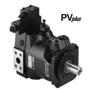
us Parker Plunger Pump Pv016r1k1t1nmmc for Sale at Low Price


Related Products
-
 American Parker Plunger Pump Pv140r9k1t1nmmck0025 AvailableUS$ 2215.38 - 2230.77MOQ: 1 Unit
 -
Danfoss Piston Pump D1p-260-r-a-tpsn-t-e4-y3-c5-100-250-25-nn-fs-fs-nnn-nnnUS$ 752 - 769.23MOQ: 1 Unit
-
Danfoss Piston Pump D1p260ratpe2te4y3b1 100320nnnnfs05nnnnnnUS$ 752 - 769.23MOQ: 1 Unit
-
Danfoss Plunger Pump D1p-145-r-a-tpsn-t-d4-n1-nn-050-250-22-nn-fs-fs-nnn-nnnUS$ 752 - 769.23MOQ: 1 Unit
-
Danfoss Piston Pump D1p-193-r-a-tpsn-t-e4-y2-a1-120-280-22-nn-fs-fs-nnn-nnnUS$ 752 - 769.23MOQ: 1 Unit
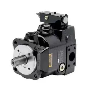
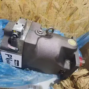
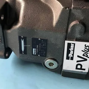
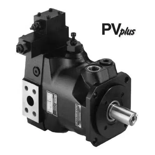
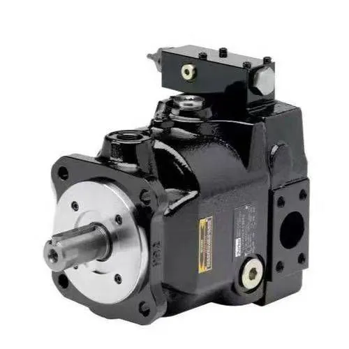
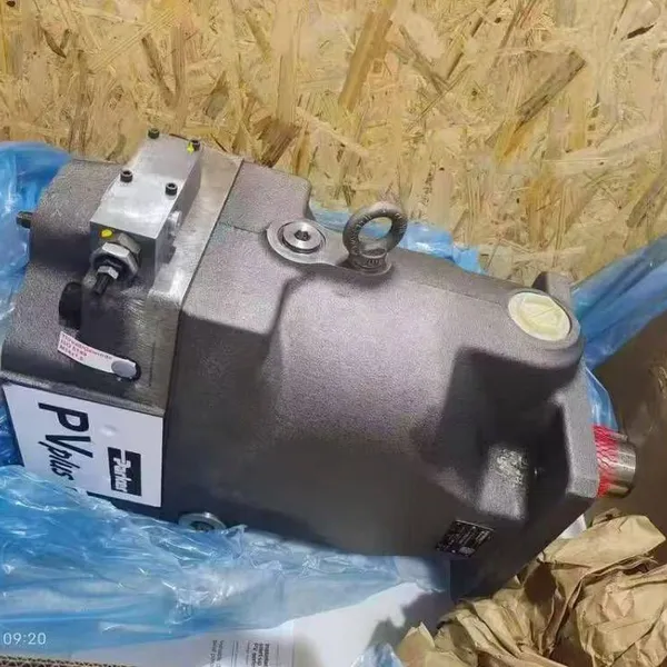
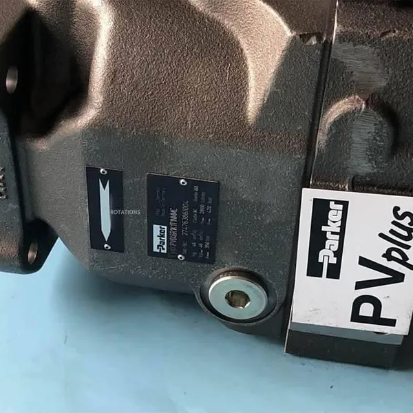
Original PV016R1K1T1NMMC Parker Piston Pump
PV016R1K1T1NMMC is a swashplate axial piston pump produced by Parker. It belongs to the high-performance variable piston pumps in the PV series and is widely used in construction machinery, industrial hydraulic systems, and heavy equipment. This pump adopts advanced variable displacement technology, which can efficiently adjust the flow rate and pressure under different working conditions to achieve a balance between energy saving and stable operation.
Main technical parameters:
Displacement: 16.0 ml/rev
Nominal working pressure: 350 bar
Minimum speed: 300 rpm
Installation method: Supports both metric and imperial standards and is compatible with various equipment interfaces.
Drain port direction: Designed to face upwards for easy installation and maintenance.
Core advantages:
High responsiveness: Equipped with a large-sized variable control piston and a strong return spring to ensure rapid pressure compensation and system stability.
Low-noise operation: The pump body structure is optimized through FEM (Finite Element Analysis), and the pre-compression volume technology is introduced to significantly reduce the operating noise and flow pulsation.
High reliability: High-quality materials and precision machining processes are used, which support long-term continuous operation and are suitable for high-pressure and high-load scenarios.
Diverse control options: Supports the configuration of standard pressure regulators or power regulators to meet the needs of different working conditions.
Typical application scenarios:
Construction machinery (such as excavators, road rollers)
Ship lifting and winch systems
Continuous rolling mills and presses in steel plants
Wind turbine pitch control systems
Railway maintenance machinery and test bench devices
Matters for installation and maintenance of PV016R1K1T1NMMC:
PV016R1K1T1NMMC is a swashplate axial piston variable pump produced by Parker. Correct installation is crucial for its operation stability, service life, and system efficiency. Considering its engineering and technical characteristics, the installation needs to focus on five key aspects: alignment accuracy, oil circuit connection, oil drain treatment, fastening method, and start-up specification.
I. Preparation before installation
Clean the system: Ensure that the cleanliness of the hydraulic oil reaches ISO 4406 18/15 level or above. It is recommended to use a filter with β₁₀ ≥ 75 to prevent contaminants from entering the pump body.
Check oil compatibility: Use anti-wear hydraulic oil that meets DIN 51524 standards (such as ISO VG 32 or VG 46). The seals are made of NBR (nitrile rubber). Avoid using ester-based oils.
Manually turn the shaft: Before installation, turn the drive shaft by hand to confirm that there is no jamming and ensure that the internal components are not damaged during transportation.
II. Key points for mechanical installation
Installation direction and orientation of the oil drain port
The oil drain port must be installed facing upwards (tilt angle ≤ 30°) to ensure that there is no residual air in the housing and avoid lubrication failure.
If inclined installation is required, ensure that the oil drain cavity is always at the highest point to prevent cavitation.
Shaft alignment accuracy
When using a coupling for connection, the radial deviation ≤ 0.1 mm and the angular deviation ≤ 1°.
It is recommended to use a flexible coupling to avoid the vibration of the engine or motor being transmitted to the pump body, causing early wear of the bearings.
Flange and bolt tightening
Adopt the SAE B2 or B4 flange installation standard. Pre-tighten the bolts diagonally and gradually tighten them to the specified torque (refer to the manufacturer's manual).
It is prohibited to forcibly tap or apply lateral force during assembly to prevent deformation of the cylinder block or valve plate.
III. Oil circuit and pipeline connection
Suction pipeline
Make it as short and straight as possible. The inner diameter should not be smaller than the pump port size. Avoid using reducing joints.
The suction pressure shall not be lower than -0.3 bar (gauge pressure) to prevent cavitation.
Discharge pipeline
Install high-pressure hoses or rigid pipes. It is recommended to install a pulsation damper to reduce the impact of flow pulsation.
Drain pipeline
Return the oil separately to the oil tank. It is prohibited to share the return pipe.
The drain pipe should be directly connected below the oil level in the tank, and the end should be at least 100 mm away from the tank bottom to prevent foam generation.
IV. Startup and debugging
Before the first startup
Fill the pump housing with hydraulic oil through the oil drain port to ensure initial lubrication of the bearings and slippers.
Close the main relief valve of the system and let the pump run at the lowest pressure for 5 minutes, then gradually increase the pressure to the working pressure.
No-load operation
First, run at a low speed (≤ 500 rpm) and observe for any abnormal noise or vibration.
After confirming that there is no leakage and the temperature rise is normal (≤ 15°C), gradually load to the rated working condition
PV140R1K1T1NMMC Parker Piston Pump
PV140R1K1T1VUPM
PV140R1K1T1VUPK
PV140R1K1T1NUPM
PV140R1K1T1VFPV
PV140R1K1T1NUPF
PV140R1K1T1NUPP
PV140R1K1T1NUPR
PV140R1K1T1NUPK
PV140R1K1T1VMTK
PV140R1K1T1NULK
PV140R1K1T1NWCK
PV140R1K1T1NMCCX5947
PV140R1K1T1NMFCX5889
PV140R1K1T1NMLW
PV140R1K1T1NMMK
PV140R1K1T1NMRK
PV140R1K1T1NSCCX5947
PV140R1K1T1NSLK
PV140R1K1T1NTLW
PV140R1K1T1NZLW
PV140R1K1T1VMMCX5899
PV140R1K1T1NKCC
PV140R1K1T1NKC1
PV140R1K1T1NMC1
PV140R1K1T1NMLZ
PV140R1K1T1NML1
PV140R1K1T1NMMCX5889
PV140R1K1T1NMMW
PV140R1K1T1NMT1
PV140R1K1T1NSC1
PV140R1K1T1NSL1
PV140R1K1T1NTC1
PV140R1K1T1NTL1
PV140R1K1T1NUC1
PV140R1K1T1NULZ
PV140R1K1T1NUL1
PV140R1K1T1NWL1
PV140R1K1T1NYC1
PV140R1K1T1NYLZ
PV140R1K1T1NYL1
PV140R1K1T1NZLC
PV140R1K1T1NZL1
PV140R1K1T1VMRCX5899
PV140R1K1T1WMFC
PV140R1K1T1WMMW
PV140R1K1T1WMR1
PV140R1K1T1NFPV
PV140R1K1T1WSCC
PV140R1K1T1WUCC
PV140R1K1T1WULC
PV140R1K1T1NMTK
PV140R1K1T1WMCK
PV140R1K1T1NYLK
PV140R1K1T1NULC
PV140R1K1T1NMLC
PV140R1K1T1NULCX5889
PV140R1K1T1NZCC
PV140R1K1T1NMCC
PV140R1K1T1NSCC
PV140R1K1T1NTCC
PV140R1K1T1NUCC
PV140R1K1T1NWCC
PV140R1K1T1NYCC
PV140R1K1T1NKLC
PV140R1K1T1NSLC
PV140R1K1T1NTLC
PV140R1K1T1NWLC
PV140R1K1T1NYLC
PV140R1K1T1NMCK
PV140R1K1T1NMTP
PV140R1K1T1NSCB
PV140R1K1T1NWCB
PV140R1K1T1NMCW
PV140R1K1T1NMFZ
PV140R1K1T1NMMCX5899
PV140R1K1T1NMMZ
PV140R1K1T1NMM1
PV140R1K1T1NMRZ
PV140R1K1T1NUCCX5889
PV140R1K1T1NZCB
PV140R1K1T1NSLW
PV140R1K1T1NWCW
PV140R1K1T1NKLB
PV140R1K1T1NMLB
PV140R1K1T1NULB
PV140R1K1T1NSCZ
PV140R1K1T1WKLC
PV140R1K1T1WMCC
PV140R1K1T1NMRC

Send Inquiry to This Supplier


You May Also Like
-
Danfoss Piston Pump D1p-130-r-a-tpe5-t-d4-n1-b1-095-340-nn-nn-fs-fs-nnn-nnnUS$ 752 - 769.23MOQ: 1 Unit
-
Danfoss Piston Pump D1p145ranpsnpd4n1nnnnn35020nnfsfsnnnnnn, Now AvailableUS$ 752 - 769.23MOQ: 1 Unit
-
Danfoss Piston Pump D1p193ranpsnpe4 y2 Nnnnn30020nnfsfsnnnnnn, Now AvailableUS$ 752 - 769.23MOQ: 1 Unit
-
Danfoss Piston Pump K2l025cpc16nnnnn3c2nsa6naaannnnnnUS$ 752 - 769.23MOQ: 1 Unit
-
Danfoss Piston Pump H1p250laaa3c2nd8cg2h6l35wp24pnnnnUS$ 752 - 769.23MOQ: 1 Unit
-
Danfoss Piston Pump H1p250laaa3c2nd8cg2h4l35l35wp24pnnnnnnn NowUS$ 752 - 769.23MOQ: 1 Unit
-
German Imported Hawe Explosion-proof Multi-way Valve Psv61/300-5 -52 h 160/160 A280 B150/ea-e1-x 24tex4 0fmUS$ 1615.38 - 1630.77MOQ: 1 Piece
-
German Imported Hawe Explosion-proof Multi-way Valve Psv3 S/300-2 -a2 l 40/40/a/2 NowUS$ 1615.38 - 1630.77MOQ: 1 Piece
-
German Imported Hawe Explosion-proof Multi-way Valve Psv3 S/300-2 -a2 l 40/40/a/2US$ 1615.38 - 1630.77MOQ: 1 Piece
-
German Imported Hawe Multi-way Valve Psl62/300-5 -55h190/190a280b280/ea2-e1-g24US$ 1615.38 - 1630.77MOQ: 1 Piece


