

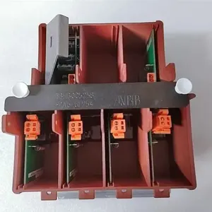
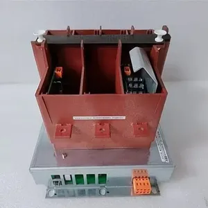
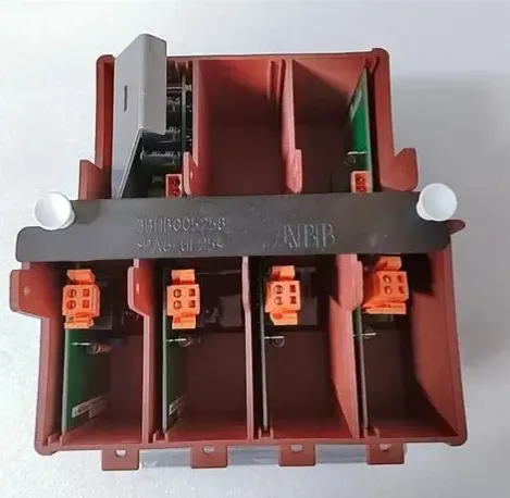
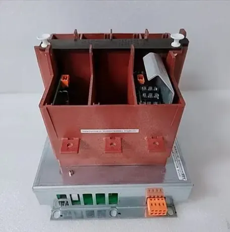
ABB KUC755AE105 3BHB005243R0105 Gate Unit Power Supply Module
Related Products
-
 ABB ICSF08D1 FPR3323101R1012 24VDC Standard RepairNegotiableMOQ: 1 Piece
 -
ABB SUE3000 1VCR007346 G0028 Communication UnitNegotiableMOQ: 1 Piece
-
ABB 5SDD1060F0001 Diode Disc ModuleNegotiableMOQ: 1 Piece
-
ABB REM610C55HCNN02 Motor Protection RelayNegotiableMOQ: 1 Piece
-
ABB UNS2880B-P V1 3BHE014967R0001 Control BoardNegotiableMOQ: 1 Piece
I. Overview
ABB KUC755AE105 3BHB005243R0105 is an embedded communication and data transmission card. As the core hub for data interaction within the system and between the system and external devices, it undertakes the key responsibilities of real-time data acquisition, high-speed signal transmission, control command forwarding, and multi-device coordinated linkage. Adopting a standardized embedded installation design, this product can be seamlessly integrated into the ABB DCS system rack, featuring excellent system compatibility and expandability, and can meet the communication and data transmission requirements in different industrial scenarios.
Equipped with a complete built-in system memory, the module has large-capacity data storage and high-speed transmission capabilities, which can accurately meet the stringent requirements of real-time control systems for data transmission timeliness and stability. It can directly connect with various industrial sensors and actuators to achieve real-time acquisition of on-site data and precise issuance of control signals; meanwhile, it supports efficient data exchange with other control devices and upper monitoring systems, constructing a complete closed-loop of industrial automation control. With its high reliability and strong environmental adaptability design, this module can operate stably in harsh industrial environments, and is widely used in industrial automation scenarios requiring real-time communication and data transmission such as power, petrochemical, metallurgy, and intelligent manufacturing. It is one of the core components ensuring the efficient and coordinated operation of the ABB distributed control system.
II. Product Features
High-speed Data Transmission Capability: Equipped with high-performance data transmission chips and optimized communication protocols, it has high-speed data sending and receiving capabilities, which can realize fast transmission of large volumes of real-time data, ensure the timeliness of data interaction in real-time control systems, and avoid control deviations caused by data delays.
Large-capacity Data Storage and Processing: Built with a complete system memory architecture and sufficient storage space, it can temporarily store massive collected on-site data, and support preliminary filtering and preprocessing of data, reducing the data processing pressure of the upper system and improving the overall system operation efficiency.
Multi-device Compatibility and Flexible Interconnection: With rich interface resources, it can directly establish stable connections with various industrial sensors (such as pressure sensors, temperature sensors) and actuators (such as solenoid valves, contactors). It also supports communication interconnection with other control modules, upper monitoring systems, remote IO devices, etc., realizing multi-device collaborative work.
High Reliability and Strong Environmental Adaptability: Adopting industrial-grade hardware design and strict quality control standards, it has excellent anti-electromagnetic interference capability and environmental adaptability. It can operate stably for a long time in harsh industrial environments such as high and low temperatures, high humidity, and heavy dust, effectively reducing the impact of extreme environments on data transmission and communication stability.
Convenient Integration and Operation & Maintenance Design: Adopting a standardized embedded installation structure, it can be quickly integrated into the ABB DCS system rack, simplifying the system deployment process; the module has a complete status monitoring function, which can feed back its own operating status in real time, facilitating operation and maintenance personnel to detect and handle abnormalities in a timely manner and reducing operation and maintenance costs.
III. Technical Parameters
1. Core Basic Parameters
Product Model: KUC755AE105 3BHB005243R0105
Series: Companion Card for ABB Distributed Control System (DCS)
Product Type: Embedded Communication and Data Transmission Card
Manufacturer: ABB
Installation Method: Standardized Embedded Installation (Compatible with ABB DCS System Rack)
Core Functions: Data acquisition, high-speed data transmission, control command forwarding, multi-device communication interconnection
2. Electrical Performance Parameters
Supply Voltage: 24V DC (Industrial Standard Power Supply, Compatible with Conventional On-site Power Supply Environment)
Power Consumption: Typical Value ≤ 5W (No-load State), Maximum Value ≤ 8W (Full-load Data Transmission State)
Memory Capacity: System Memory ≥ 16MB (Meeting the Requirements of Large-capacity Temporary Data Storage)
Data Transmission Rate: ≥ 100Mbps (High-speed Transmission Mode, Ensuring Real-time Data Interaction Requirements)
Signal Interface Type: Supporting Multiple Commonly Used Industrial Interfaces such as RS-485 and Ethernet (Subject to the Actual Product)
Communication Protocol: Supporting Mainstream Industrial Communication Protocols such as Modbus and Profinet (Meeting Multi-device Interconnection Requirements)
3. Environmental and Physical Parameters
Operating Temperature: -20℃ to +65℃ (Industrial-grade Wide-temperature Design, Compatible with Complex On-site Environments)
Storage Temperature: -40℃ to +85℃
Relative Humidity: 5% to 95% (Non-condensing, Adapting to High-humidity Industrial Scenarios)
Protection Class: IP20 (Module Body, Suitable for Installation Inside Control Cabinets)
Electromagnetic Compatibility: Complying with IEC 61000 Series Industrial Electromagnetic Compatibility Standards with Strong Anti-interference Capability
Module Dimensions: Standardized Card Dimensions, Length × Width × Height ≈ 150mm × 100mm × 30mm (Subject to the Actual Product)
Weight: Approximately 0.3-0.5kg (Subject to the Actual Product)
IV. Working Principle
The core working principle of the ABB KUC755AE105 3BHB005243R0105 embedded communication and data transmission card is a full-process data interaction closed-loop of "data acquisition - signal processing - high-speed transmission - command execution - status feedback". Through the coordinated work of internal core chips and external interfaces, it realizes efficient data flow within the system and between the system and external devices. The specific working process can be divided into five core stages:
The first stage is the data acquisition stage: The module connects with on-site sensors (such as pressure, temperature, flow sensors) through various interfaces to collect various physical quantity signals (analog or digital) of the industrial field in real time; at the same time, it receives the operating status signals fed back by actuators. All collected signals are filtered, amplified and shaped by the internal signal conditioning circuit to eliminate signal noise caused by on-site electromagnetic interference, ensuring the accuracy and reliability of raw data.
The second stage is the data processing and storage stage: The conditioned signals are transmitted to the internal core processing unit of the module. The processing unit performs format conversion, preliminary filtering and classification processing on the data, converting the raw signals into digital data recognizable by the system; meanwhile, the processed massive data is temporarily stored in the built-in system memory to avoid data loss and provide data cache support for subsequent high-speed transmission.
The third stage is the high-speed data transmission stage: Through optimized communication protocols and high-speed transmission channels, the module transmits the processed on-site data to the upper monitoring system or other control modules in real time to provide data support for system decision-making; it also receives control commands issued by the upper system or core controller to ensure the timeliness of command transmission and meet the requirements of real-time control. In this process, the module performs integrity verification on the transmitted data through the verification mechanism of the communication protocol to avoid data loss or errors during transmission.
The fourth stage is the command forwarding and execution stage: After parsing and processing the received control commands, the module accurately forwards them to on-site actuators (such as solenoid valves, servo drives) through corresponding interfaces, driving the actuators to complete corresponding control actions and realizing precise control of industrial field equipment; at the same time, the module can feed back the command forwarding status to the upper system to ensure the traceability of command execution.
The fifth stage is the status monitoring and abnormal feedback stage: The module monitors its own operating status in real time (such as power supply status, communication link status, memory usage status, etc.) as well as the connection status with external devices; if problems such as communication interruption, data transmission errors, and power supply abnormalities are detected, the module will immediately trigger an abnormal alarm mechanism, and feed back the alarm information to the operation and maintenance terminal or upper system through preset channels, facilitating operation and maintenance personnel to intervene and handle in a timely manner and ensuring the stable operation of the system.
V. Common Troubleshooting
1. Data Transmission Interruption/Data Loss
Phenomenon: The data transmission between the module and the upper system or on-site devices is suddenly interrupted, the upper system cannot obtain real-time on-site data, or the issued control commands cannot be transmitted to the actuators; data loss and errors frequently occur during data transmission, resulting in abnormal system control.
Causes: Communication link faults (such as damaged communication cables, poor contact, loose interfaces); mismatched communication protocol configurations (such as inconsistent baud rates, address codes, data formats); severe electromagnetic interference between the module and external devices; abnormalities of the built-in memory of the module or faults of the core processing chip; unstable supply voltage leading to abnormal operation of the module.
Solutions: 1. Check whether the communication cables are damaged or aged, re-plug the communication interfaces and tighten the connecting screws to ensure good contact; replace damaged communication cables, and preferentially select shielded cables to improve anti-interference ability; 2. Verify the communication protocol parameters (baud rate, address code, data bit, parity bit, etc.) of the module, upper system and on-site devices to ensure that the parameters are completely consistent; 3. Check the on-site electromagnetic interference sources (such as frequency converters, high-power relays), separate the communication cables from power cables during wiring, and install shielding layers or filtering devices if necessary; 4. Restart the module and associated devices, and observe whether the data transmission returns to normal; if the problem persists, check the memory usage status of the module and clean redundant data through system tools; 5. Use a multimeter to measure the supply voltage of the module to ensure it is 24V DC and stable, and troubleshoot the problems of poor contact or voltage fluctuation of the power supply line; 6. If the above measures are ineffective, the core processing chip of the module may be faulty, and it is necessary to contact ABB official after-sales service for repair or replacement.
2. Failure to Collect On-site Data/Incorrect Data Acquisition
Phenomenon: The module cannot collect signals from on-site sensors, and the upper system displays data missing; the collected data deviates greatly from the actual on-site status, with abnormal data fluctuations that cannot reflect the real working conditions.
Causes: Wiring errors between sensors and the module (such as reversed positive and negative poles, disconnected signal lines); sensor faults (such as open circuit, damage, mismatched range); faults of the module signal conditioning circuit that cannot normally process raw signals; incorrect acquisition parameter settings (such as inappropriate sampling frequency and range settings).
Solutions: 1. Disconnect the power supply, verify the wiring method between sensors and the module, correct reversed lines, and re-tighten disconnected terminals; 2. Test the performance of sensors separately, use a standard signal source to test whether the output signals of sensors are normal; if the sensors are faulty, replace them with sensors of the same model; 3. Check the acquisition parameter settings of the module to ensure that parameters such as sampling frequency and range match the sensors and on-site working conditions; 4. If it is suspected that the module signal conditioning circuit is faulty, the sensors can be connected to other normal modules for testing; after confirming the faulty module, contact after-sales service for repair or replacement.
3. Module Failure to Communicate with Upper System/Unrecognized
Phenomenon: The upper system cannot recognize the KUC755AE105 module and cannot establish a communication connection; the status of the module communication indicator is abnormal (not lit or flashing constantly); the system reports an error "communication device not connected".
Causes: Incorrect module address configuration, conflicting with addresses of other devices in the system; unconnected communication link between the module and the upper system (such as switch faults, incorrect routing configuration); abnormal module power supply resulting in failure to start normally; damaged module communication chip or abnormal internal program.
Solutions: 1. Verify the module address through the system configuration tool to ensure the address is unique and within the system recognition range, and modify conflicting addresses; 2. Check the operating status of switches, routers and other devices in the communication link, test the connectivity of the communication link, and repair link faults; 3. Check the supply voltage and power supply line of the module to ensure the module is powered on normally, and observe whether the module power indicator is on normally; 4. Restart the module and the upper system, and try to establish a communication connection again; 5. If the module is still unrecognized, the communication chip may be damaged or the program may be abnormal, and it is necessary to contact ABB after-sales service for program refresh or module replacement.
4. Module Overheating/Frequent Alarms
Phenomenon: The surface temperature of the module rises rapidly during operation, exceeding the normal operating temperature range; overheating alarms or irregular alarms are frequently triggered, affecting the normal operation of the system.
Causes: Poor ventilation in the module installation environment and blocked heat dissipation channels; excessively high on-site ambient temperature exceeding the upper limit of the module operating temperature; long-term full-load operation of the module resulting in excessive power consumption; faults of internal heat dissipation components of the module (such as falling off heat sinks, stopped fans); abnormal internal circuits of the module leading to increased energy consumption.
Solutions: 1. Immediately check the module installation environment, clean dust and debris on and around the module to ensure unobstructed heat dissipation channels; 2. Check the on-site ambient temperature; if it exceeds 65℃, install cooling fans or improve ventilation conditions to reduce the ambient temperature; 3. Troubleshoot the load condition of the module; if it operates at full load for a long time, optimize the system design, distribute data transmission pressure, and avoid overload operation of the module; 4. Check the internal heat dissipation components of the module; if the heat sinks fall off or the fans fail, repair or replace them in a timely manner; 5. If the module still overheats frequently, the internal circuit may be abnormal; stop using it and contact ABB after-sales service for testing and repair.

Send Inquiry to This Supplier


You May Also Like
-
ABB UFC718AE01 HIEE300936R0101 Main Circuit Interface BoardNegotiableMOQ: 1 Piece
-
ABB RF522 3BSE000743R1 Including BackplaneNegotiableMOQ: 1 Piece
-
ABB UFC760BE41 3BHE004573R0141 Interface BoardNegotiableMOQ: 1 Piece
-
ABB PFTL201C-50KN 3BSE007913R50 Pressure SensorNegotiableMOQ: 1 Piece
-
ABB 5SHY3545L0016 3BHB020720R0002 Integrated Gate-Commutated Thyristor (IGCT)NegotiableMOQ: 1 Piece
-
ABB 3BHE019719R0101 GVC736BE101 Integrated Gate-Commutated Thyristor (IGCT)NegotiableMOQ: 1 Piece
-
ABB 216NG61A HESG441633R1 HESG216875/K Main Control BoardNegotiableMOQ: 1 Piece
-
ABB PFEA113-65 3BSE050092R65 Tension ElectronicsNegotiableMOQ: 1 Piece
-
ABB UAD142A01 3BHE012551R0001 Analog Input ModuleNegotiableMOQ: 1 Piece
-
ABB RXIDK 2H 1MRK000838-HA Relay ModuleNegotiableMOQ: 1 Piece


