

SVG is Applied in the Rolling Mill of a Stainless Steel Company


Related Products
-
 The Power Factor of a Certain Power Supply Station Increased to More Than 0.98 After Using SVGNegotiableMOQ: 1 Combo
 -
Aodong ADSVG Solves the Problem of Power Grid Voltage Drop and Improves the Power Factor to 0.98 or AboveNegotiableMOQ: 1 Combo
-
Aodong ADSVG Compensates the Reactive Power of the System to Improve the Stability of Line TransmissionNegotiableMOQ: 1 Combo
-
Aodong Electric ADSVG Dynamic Reactive Power Compensation Device With Bidirectional CompensationNegotiableMOQ: 1 Combo
-
Technical Parameters, Protection Functions and Operating Environment of Aodong Electric ADSVGNegotiableMOQ: 1 Combo
A stainless steel company specializes in manufacturing medium-sized stainless steel plates, producing approximately 170-180 ingots daily with each weighing 2-5 tons. The facility operates a main transformer rated at 12,000 kVA, primarily powering two roll-type rolling mills driven by dual DC motors (4,200 kW each). During operation, these mills generate substantial reactive power, causing reduced line power factor at the company's electrical input. Rapid fluctuations in active and reactive power also induce grid voltage flicker. The DC motors utilize a non-controlled rectifier circuit with power electronic components at their front end, which produces significant harmonic pollution. This necessitates comprehensive power quality management measures including reactive power compensation, grid voltage flicker suppression, and harmonic mitigation. The original system employed an integrated solution combining MCR (Multichannel Rectifier), filter branches, and FC (Frequency Controller) compensation for load regulation. However, the limited response speed of the MCR system prevents rapid compensation for the rolling mills' transient reactive power demands.
The connection diagram of the field power distribution system is shown in the figure.
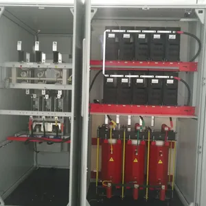
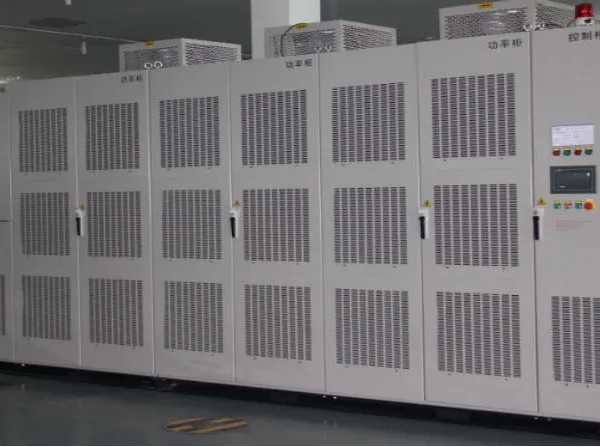
The original power distribution compensation system adopted a combined compensation scheme of FC, filter branch, and MCR. The FC had a capacity of 4000 kvar, while the filter branches (with capacities of 5th order 2100 kvar, 7th order 1700 kvar, 11th order 700 kvar, and 13th order 700 kvar) were configured accordingly. The MCR was selected with a compensation capacity of 4500 kvar. After commissioning this compensation system, the total power factor improved to over 0.85, but occasional instantaneous reactive power shortages occurred. Field tests revealed that standard MCRs have response times exceeding 200ms. When the rolling mill is idle, the MCR's inductive rated reactive power precisely compensates for the capacitive reactive power from the FC and filter branches. During mill operation, within milliseconds, the MCR must deliver over 4000kvar of inductive reactive power. At this critical moment, the MCR cannot rapidly reduce its own 4500kvar inductive reactive power. This results in superimposed reactive power from both the rolling mill and MCR, causing significant inductive reactive output in the system and further voltage reduction in the grid.
Because the response speed of MCR can not meet the requirements of rapid compensation, the power grid voltage flicker has not been well suppressed. The obvious light flickering phenomenon can be seen from the factory lighting situation. Voltage flicker will lead to uneven output of rolling mill, affecting the production efficiency and product quality in the factory.
The active and reactive power curves of the rolling mill during operation without the compensation device are shown in the figure, with data collected every minute at a sampling interval of 1 second. The effective voltage curve of the grid during operation without the compensation device is shown in the figure, with data collected every minute at a sampling interval of 1 second.
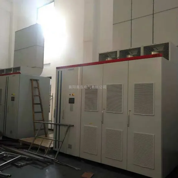
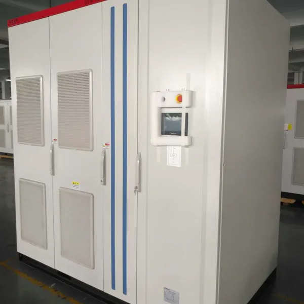
In view of the above situation, in order to further improve the power factor in the plant, reduce the possibility of power company fines, reduce the flicker of the power grid, and improve the production efficiency of the rolling mill, a stainless steel company selected SVG (3Mvar/10kV), combined with the filter branch, and FC branch is occasionally put into use according to the situation.
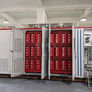
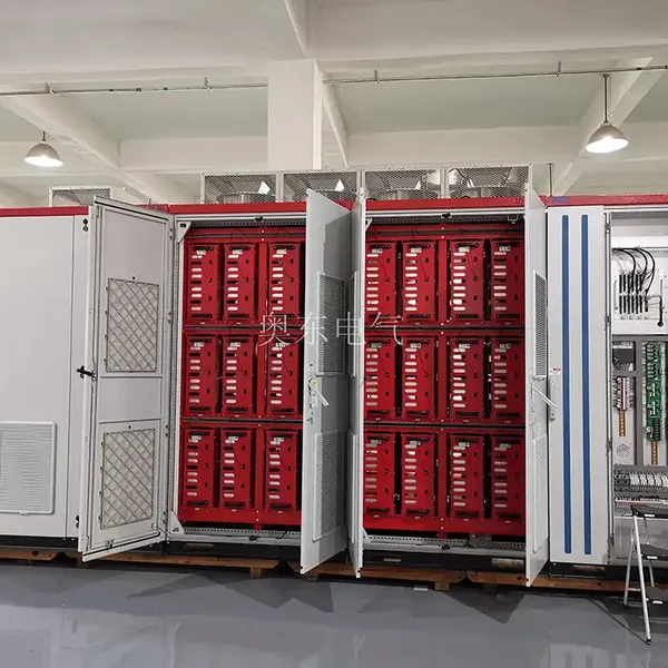
Although the SVG capacity is smaller than the original MCR, the SVG has a fast response speed (response time less than 5ms) as shown in the figure, so there will be no short-term reactive overcompensation phenomenon, and the compensation effect is excellent.
The reactive power compensation effect is good after operation. When the maximum power of the rolling mill is running, there is occasionally about 3000kvar reactive power, and the active power is more than 11000kW. The overall power factor is more than 0.95.
After SVG operation, the power grid voltage flicker has been effectively controlled due to the fast response speed. Compared with the previous power grid voltage, the power grid voltage is significantly stable, and the maximum and minimum voltage fluctuations are not more than 400V, which has achieved a significant effect of voltage flicker suppression compared with the voltage difference of about 1000V in the uncompensated state.
The cost factor is considered in the process of project transformation, so the 3MvarSVG product with slightly lower capacity is selected. If the SVG capacity is selected as 5Mvar or other products with large power levels, the voltage fluctuation suppression effect of the power grid will be better, and the power factor of the power grid can be improved even higher.

Send Inquiry to This Supplier

You May Also Like
-
Introduction to the ADSVG System Architecture of Aodong ElectricNegotiableMOQ: 1 Combo
-
Aodong Electric ADSVG Field Electrical InstallationNegotiableMOQ: 1 Combo
-
Trouble Shooting for ADSVG InAodong ElectricNegotiableMOQ: 1 Combo
-
Structure and Advantages of ADSVG High-voltage Dynamic Reactive Power Compensation DeviceNegotiableMOQ: 1 Combo
-
Aodong Electric ADSVG Rolling Mill Dynamic Reactive Power Compensation Application CaseNegotiableMOQ: 1 Combo
-
Aodong Electric ADSVG Photovoltaic Power Generation Field Application CaseNegotiableMOQ: 1 Combo
-
Aodong Electric ADSVG Electric Arc Furnace Field Application CaseNegotiableMOQ: 1 Combo
-
Aodong Electric ADSVG Urban Power Transmission and Distribution Application CaseNegotiableMOQ: 1 Combo
-
Aodong Electric ADSVG Submerged Arc Furnace Field Application CaseNegotiableMOQ: 1 Combo
-
Aodong Electric ADSVG Wind Power Field Application CaseNegotiableMOQ: 1 Combo


