








 Contact Platform Support
 Help Center
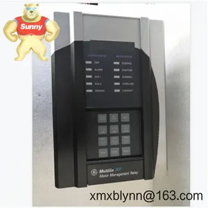
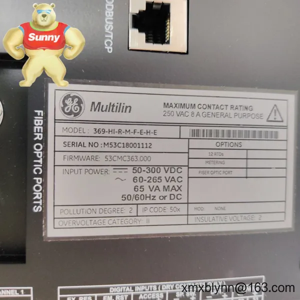
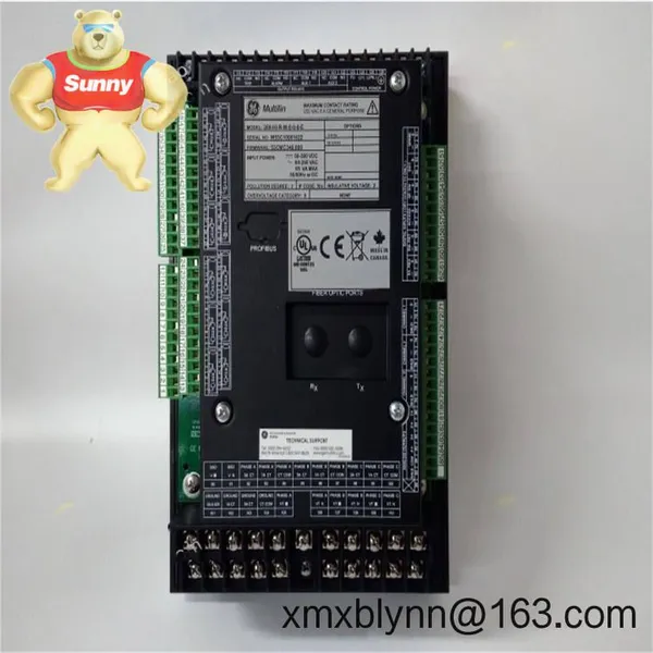
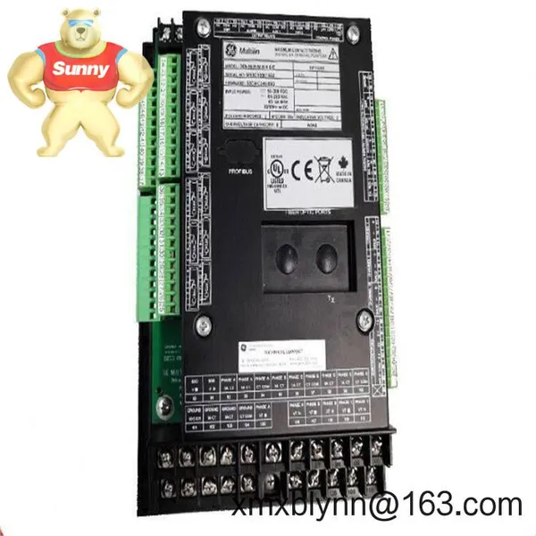
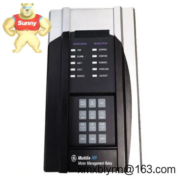
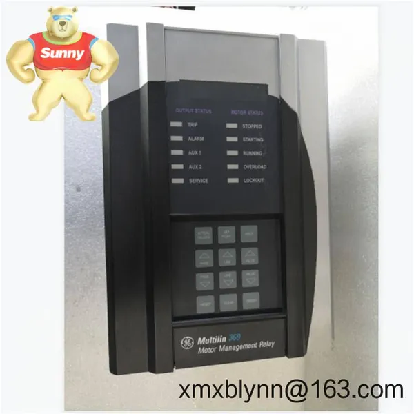
GE Multilin 369-HI-R-M-0-0-0 Motor Management Relay – Smart Protection and Monitoring for Critical Motors



Related Products
-
 GE AT686W Industrial Controller Module – Stable Rack-mounted Control Module for GE Automation SystemsUS$ 3660.00MOQ: 1 Combo
 -
FANUC A20B-2001-0065/06A System Master Board – Core CPU/Controller Board for FANUC CNC SystemsUS$ 3216.00MOQ: 1 Blade
-
GE DS200ADPBG1ABB Genius Adapter Board – Reliable Genius Bus Interface for Mark V and GE Drive SystemsUS$ 3216.00MOQ: 1 Blade
-
GE DS200CTBAG1ADD – Contactor/Terminal Board for Reliable Discrete I/O TerminationUS$ 3216.00MOQ: 1 Blade
-
GE DS200DCFBG1BKC – Power Distribution/Power Supply Board for Mark V CabinetsUS$ 3216.00MOQ: 1 Blade
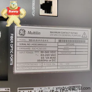
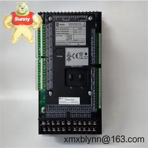
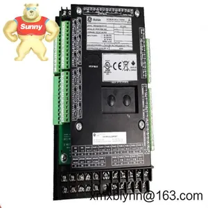
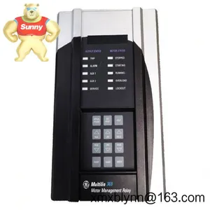
The GE Multilin 369-HI-R-M-0-0-0 is a dedicated motor management relay designed to protect and optimize low and medium-voltage three-phase motors. It combines protective functions, metering, and event recording so maintenance teams can see what’s happening before downtime strikes. From my experience, it’s typically selected for pumps, fans, conveyors, and compressors where start profiles, load behavior, and thermal limits actually matter.
The 369 platform is known for dependable thermal modeling, robust RTD temperature monitoring, and straightforward communications. The option code “HI-R-M-0-0-0” appears to be a common build variant in the field; in many cases it indicates high-current CT inputs, relay outputs, and Modbus communications, though it’s wise to confirm options against the unit’s nameplate if you’re matching an installed base.
Key FeaturesComprehensive motor protection – Thermal overload, jam, stall, underload, current imbalance, and ground fault protection help guard motors during start and normal operation.
Integrated temperature monitoring – Supports multiple RTDs (typically Pt100) for stator and bearing temperature feedback, letting you trip or alarm before thermal damage escalates.
Event, waveform, and data logging – Stores trips, alarms, and key motor statistics; in most cases you can pull this data via software for quick root-cause analysis.
Accurate metering – Real-time current, demand, thermal capacity used, and start counters help you tune settings and plan maintenance windows with fewer guesswork.
Flexible I/O – Discrete inputs for status signals, relay outputs for trip/alarms, and typically 4–20 mA outputs for analog indication back to DCS/PLC.
Industrial communications – RS-485 Modbus RTU is common; many units also support Ethernet-based connectivity or other fieldbuses depending on options installed.
Rugged build for switchgear – Designed for panel mounting in MCCs and switchgear, with firmware features aligned to real plant workflows.
Software tools – Typically compatible with GE Multilin configuration and commissioning tools, making setpoint management and backups straightforward.
| Brand / Model | GE Multilin 369-HI-R-M-0-0-0 Motor Management Relay |
| Power Requirements | Universal auxiliary supply, typically 110–250 Vac/Vdc (verify on nameplate for your unit) |
| Signal Inputs | 3-phase current via CTs (1 A or 5 A nominal), ground CT input, multiple RTD channels (Pt100 commonly used), digital status inputs |
| Outputs | Trip/Alarm relay outputs; typically 4–20 mA analog outputs for key values (varies by option) |
| Communication | RS-485 with Modbus RTU as standard; Ethernet/other buses available on specific builds |
| Operating Temperature | Typically −20 °C to +60 °C (check datasheet for exact rating) |
| Installation Method | Panel (flush) mounting for MCC/switchgear; draw-out case variants exist on the 369 platform |
| Dimensions & Weight | Compact relay form factor suitable for standard MCC cutouts (request exact size by sub-model) |
You’ll typically see the 369 in process plants and utilities where motor uptime is tied to throughput. It’s a good fit for:
Water and wastewater – protecting large pumps and blowers, catching jams and dry runs before they turn into failures.
Oil, gas, and petrochemical – monitoring compressor and fan motors in hazardous duty lines where a nuisance trip is expensive.
Mining and aggregates – conveyors and crushers where stall/jam detection saves belts and bearings.
Power generation – cooling tower fans and auxiliary pumps, often standardized across units for uniform settings and spares.
Pulp & paper, cement, food & beverage – anywhere repeated starts and thermal cycling can shorten motor life if not managed.
Reliability – Proven relay platform with solid thermal modeling; it seems to handle tough MCC environments well when installed correctly.
Compatibility – Works with standard 1 A or 5 A CTs, common RTDs, and Modbus networks, so integration overhead stays low.
Lifecycle cost savings – Early fault detection (jam/stall/imbalance/overtemp) typically reduces motor rewinds, process disruptions, and unplanned callouts.
Supportability – Configuration tools and abundant field experience make commissioning and future changes predictable.
Panel mounting – Install in a clean, ventilated MCC or switchgear compartment. Follow the recommended cutout and keep clearance for wiring and heat dissipation.
Wiring practices – Use shielded twisted pair for RS‑485; route CT and RTD wiring away from high-noise circuits. Verify CT polarity and burden, and land shields at a single point.
Ground fault sensing – Use a dedicated ground CT with correct ratio; set pickup and time delays to match your coordination study.
Settings management – Start with motor nameplate data and thermal curves; in many cases, you’ll fine-tune start inhibits, jam, and underload after a week of trend data.
Routine maintenance – Back up settings, review event logs monthly, check terminal tightness, and clean the bezel/vents. Schedule firmware updates during planned outages when applicable.
Safety – Isolate control power, short CTs before disconnect, and follow lockout/tagout. Confirm relay outputs are de‑energized before working on control circuits.
5 A or 1 A protection-class CTs matched to feeder rating for accurate metering and protection.
Pt100 RTD sensors for stator windings and bearings, with appropriate terminal blocks and shielded cabling.
RS‑485 cabling and gateways if integrating Modbus RTU into Ethernet-based control networks.
Configuration/monitoring software for quick parameter changes, event retrieval, and report exports.
CE compliant for industrial environments
UL/cUL listed or recognized (industrial control equipment)
CSA certifications on many builds
Manufacturer’s limited warranty typically 2 years (confirm for your supplied lot)
If you’re replacing an existing relay, share the full option code from the side label so we can validate CT rating, I/O mix, and communications. Matching those details saves time during changeover and avoids rewiring surprises.

Send Inquiry to This Supplier



You May Also Like
-
GE DS200DMCBG1AED Isolation Terminal Board – Clean, Isolated Field I/O for DS200/Mark V-Based SystemsUS$ 3216.00MOQ: 1 Blade
-
GE DS200DPCBG1AAA – DS200 Series Drive/Excitation Control Module for Power and Protection InterfaceUS$ 3216.00MOQ: 1 Blade
-
GE DS200DMCBG1AKG Drive Control/Processor Board – Reliable CPU Core for GE DC/AC Drive and Exciter SystemsUS$ 3216.00MOQ: 1 Blade
-
GE DS200KLDBG1ABC LED Display Board – Status and Keypad Display Interface for Mark V / GE Industrial Drive PanelsUS$ 3216.00MOQ: 1 Blade
-
GE DS200FGPAG1AHD Gate Pulse Amplifier Board — Reliable Firing Control for GE Drive and Excitation BridgesUS$ 3216.00MOQ: 1 Blade
-
GE DS200DSPCH1ADA Digital Signal Processor Control Board – High‑speed Loop Control for GE Drive and Turbine SystemsUS$ 3216.00MOQ: 1 Blade
-
GE DS200KLDCG1AAA LED Display Board – Front-panel Status and Keypad Interface for GE DS200-based Drives and ControlsUS$ 3216.00MOQ: 1 Blade
-
GE DS200LDCCH1ALA LAN Communication Card – Stable Plant Networking for GE Drive/Excitation SystemsUS$ 3216.00MOQ: 1 Blade
-
GE DS200LDCCH1ANA – Drive Control / LAN Communication Board for GE Industrial Drives and ExcitersUS$ 3216.00MOQ: 1 Blade
-
GE DS200PCCAG9ACB – Power Supply & Control Interface Card for DS200-based Drive/Excitation SystemsUS$ 3216.00MOQ: 1 Blade


