Home > Electrical & Electronics > Electrical Control System > ABB 1MRB150005R0001 Digital I/O Module

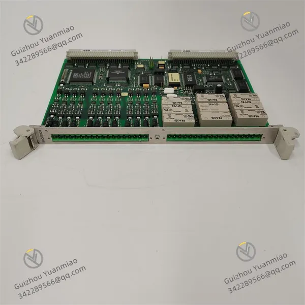
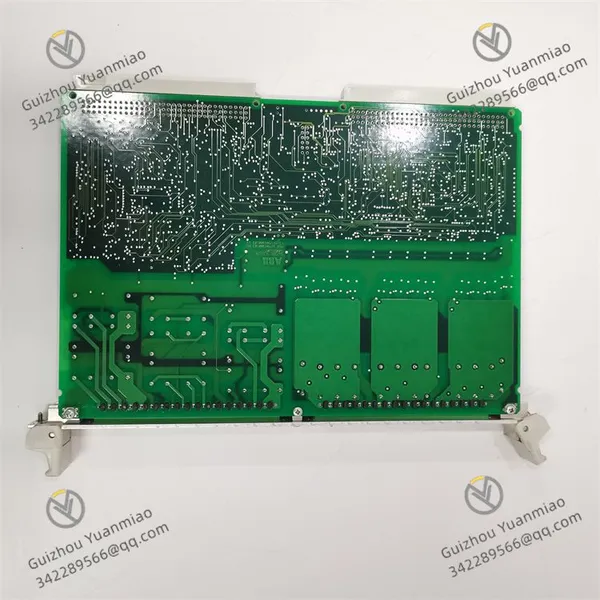
ABB 1MRB150005R0001 Digital I/O Module
ABB 1MRB150005R0001 Digital I/O Module photo-1
ABB 1MRB150005R0001 Digital I/O Module photo-2
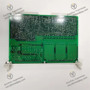
ABB 1MRB150005R0001 Digital I/O Module photo-3
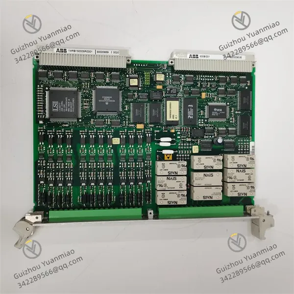
Negotiable MOQ: 1 Piece (Price negotiable depending on order volume and customization)
Key Specifications
Get Latest Price
Material:
Other, Global universal model
Condition:
Other, Global universal model
Task:
Other, Global universal model

Payment & Shipping
Payment Methods:
Port of Shipment:
China
Delivery Detail:
Delivery time depends on order quantity.
Material Other, Global universal model
Condition Other, Global universal model
Task Other, Global universal model
Mathematical Model Other, Global universal model
Signal Other, Global universal model
Customized Non-Customized
Structure Other, Global universal model
Operating Temperature -25°C–+60°C
Humidity 5%–95% (non-condensing)
Power Supply 24VDC (±20%)

I. Positioning and Applications


  • Series Affiliation: Digital input/output module of ABB AC 500 series PLC, used for processing input and output control of switching signals in industrial automation systems, suitable for scenarios such as logic control, equipment status monitoring, and safety interlocking.

  • Core Functions: Supports high-speed acquisition and driving of multi-channel digital signals, enabling real-time communication with AC 500 CPU modules via the backplane bus. It is applicable to scenarios like production line start/stop control, motor driving, and sensor signal processing.


500BIO01 1MRB150005R0001 (5)


II. Technical Parameters and Characteristics


Signal Input/Output Specifications

  • Channel Configuration: 16-channel digital input (DI) + 16-channel digital output (DO), totaling 32 channels with grouped isolation.

  • Input Characteristics:

    • Signal type: 24VDC input (ON ≥11VDC, OFF ≤5VDC);

    • Input impedance: Approximately 4.7kΩ, response time software-configurable (0.1ms–20ms).

  • Output Characteristics:

    • Output type: Transistor (NPN/PNP) or relay output (optional in different versions);

    • Driving capability: 0.5A max per channel, 4A max per group, supporting inductive loads (requires external flyback diode).


Electrical Characteristics

  • Power Supply: 24VDC (±20%), power consumption ≤8W;

  • Isolation: Electrical isolation between input/output channels and between channels and power supply (500V AC/1min), with strong anti-interference capability;

  • Filtering and Response: Input channels support software-adjustable filtering, output channel response time ≤1ms.

Mechanical and Environmental Parameters

  • Mounting Method: 35mm DIN rail mounting, supports vertical/horizontal installation;

  • Operating Temperature: -25°C–+60°C, humidity 5%–95% (non-condensing).


500BIO01 1MRB150005R0001 (2)


III. Application Scenarios


  • Logic Control: Signal acquisition for production line start/stop buttons and limit switches; switching control for motor forward/reverse rotation and solenoid valve actions.

  • Equipment Status Monitoring: Feedback on valve open/close status and circuit breaker position; fault detection for safety door interlocks and emergency stop buttons.

  • Power and Energy: Monitoring of switch status in power distribution cabinets; start/stop control of generator sets and output of protection signals.

  • Manufacturing: IO signal interaction for robots; synchronization of workstation status in automated production lines.


IV. Interfaces and Wiring


Terminal Block Design

  • Adopts detachable terminal blocks (e.g., 1SFA610001R1001), supporting screw or spring terminal connections. Input/output channels are grouped and labeled (DI1–16, DO1–16).

  • Typical Wiring:

    • Digital input: Positive pole of 24VDC sensor connected to common terminal (COM), negative pole to input terminal;

    • Digital output (transistor): One end of the load connected to 24VDC positive, the other end to the output terminal, common terminal (COM) connected to power negative.

Communication Interface

  • Communicates with CPU modules via the AC 500 backplane bus, with data refresh cycle ≤5ms, supporting real-time status feedback.


500BIO01 1MRB150005R0001 (1)


V. Configuration and Debugging


Software Tools

  • Uses ABB Control Builder AC 500 for configuration, enabling settings for:

    • Input channel filtering time, initial status of output channels (default ON/OFF on power-up);

    • Input signal disconnection detection (voltage

    • Hardware interlock for output channels (prevents misoperation).

Fault Diagnosis

  • Status Indicators:

    • Power (green): Lights up when power is normal;

    • Error (red): Flashes in case of channel faults (overload, short circuit);

    • Sync (yellow): Flashes when communication with CPU is normal;

    • Channel indicators (LED): Real-time display of input/output status (lights up when ON).


VI. Comparison with Similar Modules (vs. 500BIM01, 500BIO02)


Comparison Dimension 500BIO01 500BIM01 500BIO02
Number of Channels 16DI+16DO 16DI+16DO 32DI (no output)
Output Type Transistor/relay optional Transistor/relay optional No output (pure input)
Response Time Input/output ≤1ms Input/output ≤1ms Input ≤0.5ms
Typical Scenarios Integrated logic control and driving Integrated logic control and driving Pure status monitoring (dense sensor scenarios)
Product Tags: 500BIO01 , 1MRB150005R0001 , 1MRB150005R1/J

Send Inquiry to This Supplier

* Message
0/5000

Want the best price? Post an RFQ now!
Verified Business License
Business Type
Trading Company
Year Established
2014
Factory Size
1,000-3,000 square meters
Product Certifications
SA8000