Product Description
I. Overview
CE4002S1T2B5 is a digital output module, mainly used to accurately convert digital signals from the control system into actual control actions, drive external load devices such as relays and solenoid valves, and then realize the automatic control of various industrial production processes.
The CE4002S1T2B5 module exists as a bridge between the two. For example, in an automated assembly line, the central control system issues digital control commands according to the production process and equipment status. After receiving these commands, the CE4002S1T2B5 module quickly converts them into corresponding electrical signals, drives relays to control the start and stop of motors, the operation or stop of conveyors, etc., ensuring that the production line runs in an orderly manner and greatly improving production efficiency and product quality.

II. Technical Parameters
(1) Electrical Parameters
Output voltage: The rated output voltage is 24VDC. This voltage value is suitable for many actuators and load devices in industrial sites, and can provide stable and reliable driving energy for them, ensuring the normal operation of the equipment and the effective conversion of control signals into actual mechanical actions.
Output current: The output current of a single channel has a certain carrying capacity, which can meet the driving needs of most conventional loads such as relays and solenoid valves. For example, the working current of a common small relay is usually between tens of milliamperes and hundreds of milliamperes. The single-channel output current of the CE4002S1T2B5 module is sufficient to drive it easily, ensuring that the control command can be executed accurately.
Number of channels: The module is equipped with 32 output channels, which means it can independently control 32 different external devices or control objects at the same time. In large automated factories, a production line may involve many devices that need to be controlled individually, such as motors and valves. With its rich number of channels, the CE4002S1T2B5 module can centrally manage and precisely control these devices, effectively reducing the hardware cost and wiring complexity of the control system.
(2) Physical Parameters
Dimensions: The overall size is 263×58×28mm. The compact design can easily fit into the internal space of various industrial control cabinets. Whether it is a small on-site control box or a large central control cabinet, the module can be installed conveniently, which provides great convenience for system integration and helps build an efficient automated control system in a limited space.
Weight: The weight is about 4.3kg, which is relatively light. During installation and maintenance, operators can easily carry, install and replace it, reducing labor intensity. At the same time, it also reduces the pressure on installation brackets, cabinet structures, etc. due to the heavy weight of the module, improving the stability and reliability of the entire system.
Installation method: It supports the standard DIN rail installation method, which is a widely used installation standard in the field of industrial automation. By clamping the module on the DIN rail, the installation process is simple and fast, and it is convenient for later maintenance and repair. When the module fails and needs to be replaced, it can be quickly disassembled from the rail and replaced with a new one, minimizing equipment downtime and ensuring production continuity.
(3) Environmental Parameters
Operating temperature range: It can work normally in the ambient temperature range of -20°C to +70°C. This wide temperature adaptation range enables the module to operate stably in various complex industrial environments. Whether it is outdoor industrial facilities in cold regions or high-temperature production workshops in hot environments, such as steel smelters and glass factories, the CE4002S1T2B5 module can resist the impact of temperature changes and ensure the continuous and reliable operation of the automated control system.
Humidity adaptation: It can adapt to the environmental conditions with a relative humidity of 0% to 95% (non-condensing). In humid industrial environments, such as factories in southern coastal areas and underground sewage treatment plants, the internal circuit design and protective measures of the module can effectively prevent electrical short circuits, corrosion and other problems caused by humidity, ensuring the long-term stable operation of the module, extending its service life and reducing maintenance costs.
Protection level: Although the specific protection level is not clearly specified, from its design and application scenarios, the module has a certain ability to prevent dust and splashing water. In general industrial production environments, it can effectively resist the intrusion of dust particles and the impact of a small amount of splashing water, protecting the safety of internal circuits. If used in a more harsh environment, with an additional protective shell, its protection performance can be further improved to ensure the normal operation of the module under complex working conditions.
III. Functional Features
(1) Stable and Reliable Output Control
High anti-interference ability: It adopts advanced electrical isolation technology to build a solid barrier between the output channel and the control system, effectively resisting complex electromagnetic interference in industrial sites. In industrial environments full of strong electromagnetic interference sources such as motors and frequency converters, such as large machinery manufacturing workshops and power substations, the module can stably output control signals, avoiding signal errors or misoperations caused by electromagnetic interference, and ensuring the accuracy and stability of the control system.
Fault diagnosis and protection function: It has a built-in perfect fault diagnosis mechanism to monitor the working status of the output channel in real time. Once an abnormal situation is detected, such as output short circuit or overload, it will immediately trigger protection measures, cut off the output of the corresponding channel, and prevent the fault from expanding. At the same time, it feeds back fault information to the control system through indicator lights or communication interfaces, which is convenient for maintenance personnel to quickly locate and solve problems, greatly shortening equipment downtime and improving production efficiency.
(2) Flexible Communication Interfaces
Support for multiple communication protocols: It is fully compatible with mainstream industrial communication protocols such as Modbus TCP/IP and Profibus DP, and can be seamlessly connected to various automated control systems. In complex industrial networks composed of devices of different brands, the CE4002S1T2B5 module can perform high-speed and stable data interaction with upper computers and other intelligent devices through corresponding communication protocols, realizing information sharing and collaborative control, breaking down communication barriers between devices, and improving the integration and intelligence level of the entire automated system.
Communication interface configuration: It is equipped with an Ethernet interface and an RS485 interface. The Ethernet interface, with its high data transmission rate, is suitable for communication scenarios with large amounts of data and high real-time requirements, such as real-time data exchange with the central control system to realize functions such as remote monitoring and remote parameter setting. The RS485 interface, with its good anti-interference and multi-node connection capabilities, is often used in industrial sites to connect various sensors, intelligent instruments and other devices, building a stable and reliable data collection network, ensuring that the module can timely obtain the operating status information of on-site devices, and providing a basis for precise control.
(3) Convenient System Integration
Standard interface design: The electrical and mechanical interfaces of the module are designed in accordance with industrial standards, which can be easily realized whether connecting with external load devices or integrating with the control system. In the process of building an automated production line, engineers can quickly complete the wiring and connection work between the module and various devices according to the standard interface specifications, greatly shortening the system integration cycle and reducing project implementation costs.
Software compatibility: It supports a variety of automated programming software, such as Siemens' Step7 and Rockwell's RSLogix. Engineers can conveniently program and configure the module according to their familiar programming environment to realize flexible control of the output channels. At the same time, the module provides rich function blocks and instruction sets, which is convenient for developers to write complex control logic and meet the personalized needs of different industrial application scenarios.
IV. Common Faults and Solutions
(1) Output Abnormality
Fault phenomenon: One or more output channels cannot output signals normally, or the output signals are unstable, appearing intermittently.
Possible causes:
Channel hardware damage: Long-term use or impact of overvoltage and overcurrent may cause damage to the internal circuit components of the output channel.
Connection line failure: The connection cable between the output end and the load device may have open circuit, short circuit or poor contact.
Software configuration error: The control system has incorrect settings for the output parameters of the module, such as incorrect settings of output mode and output delay time.
Solutions:
Hardware inspection and replacement: Use professional electronic testing instruments, such as multimeters and oscilloscopes, to test the circuit of the faulty channel, identify and replace the damaged components. If the specific damaged component cannot be determined, try to replace the entire output module.
Line inspection and repair: Carefully check the connection lines to see if there are obvious cable damage, breakage or loose joints. For open-circuit cables, reconnect or replace them; for short-circuit problems, find and repair the short-circuit point; ensure all joints are firmly connected, and use tools such as crimping pliers for reinforcement if necessary.
Software parameter inspection and adjustment: Check the software configuration related to the module in the control system to confirm that the output parameters are set correctly. If the parameter settings are wrong, adjust them according to actual needs, then re-download the configuration to the module, and observe whether the output returns to normal.
(2) Communication Fault
Fault phenomenon: The module cannot establish a communication connection with the upper computer or other devices, or data loss and errors occur during communication.
Possible causes:
Communication cable failure: The communication cable is damaged, has poor contact or incorrect wiring, resulting in blocked signal transmission.
Inconsistent communication parameter settings: The communication parameters of the module and the communicating device, such as baud rate, data bit, stop bit, parity bit, etc., do not match.
Module communication chip failure: The chip responsible for communication inside the module may be damaged due to overheating, static electricity, etc.
Solutions:
Communication cable inspection and replacement: Use a cable tester to comprehensively test the communication cable, check the connectivity of the cable, whether the line sequence is correct, and whether there is signal attenuation. If a cable fault is found, replace it with a qualified communication cable in time and ensure correct wiring.
Communication parameter check and correction: Carefully check the communication parameters of the module and the communicating device to ensure that the settings of both parties are completely consistent. After adjusting the parameters, restart the communication equipment and the module, try to establish a communication connection, and observe whether the communication returns to normal.
Communication chip replacement: If it is determined that the module's communication chip is faulty after inspection, contact professional maintenance personnel or the module supplier to obtain and replace the communication chip of the same model. During the chip replacement process, attention should be paid to electrostatic protection to avoid damage to other circuit components due to improper operation.

 1YrAnshun, Guizhou, China
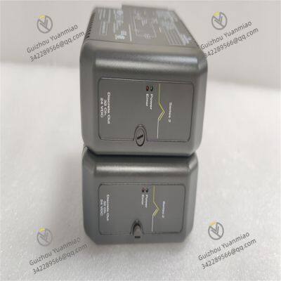


 yezi
Hi there! Welcome to my shop. Let me know if you have any questions.
yezi
Hi there! Welcome to my shop. Let me know if you have any questions.