

Home > Electrical & Electronics > Electrical Control System > GE IC697CHS770 Dual-redundant Rear-mounted Rack Module
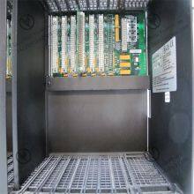
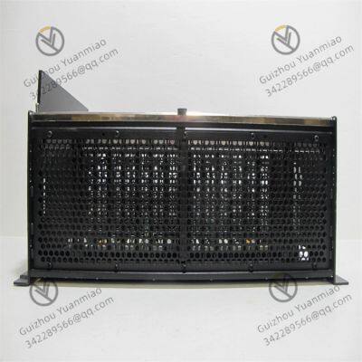
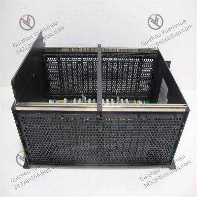
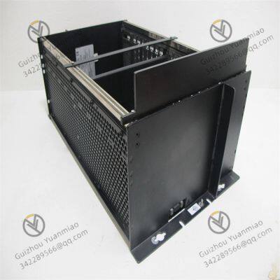
GE IC697CHS770 Dual-redundant Rear-mounted Rack Module
Negotiable
MOQ: 1 Piece (Price negotiable depending on order volume and customization)
Key Specifications
Get Latest Price
Material:
Other
Certification:
Other
Function:
Other
Payment & Shipping
Payment Methods:
Port of Shipment:
China
Delivery Detail:
Delivery time depends on order quantity.
Related Products
-
 IC693PCM311 GE Power ModuleNegotiableMOQ: 1 Piece
 -
GE IC697CMM711 Single-slot Communication Coprocessor ModuleNegotiableMOQ: 1 Piece
-
IC693PWR321 GE Power ModuleNegotiableMOQ: 1 Piece
-
IC693PWR322 GE High Performance Redundant Power ModuleNegotiableMOQ: 1 Piece
-
GE IC697CMM712 Serial Communication ModuleNegotiableMOQ: 1 Piece
Material
Other
Certification
Other
Function
Other
Condition
Other
Task
Other
Mathematical Model
Other
Signal
Other
Customized
Other
Structure
Other
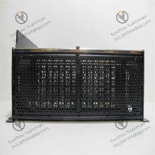
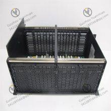
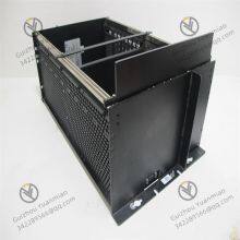
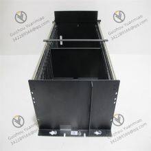
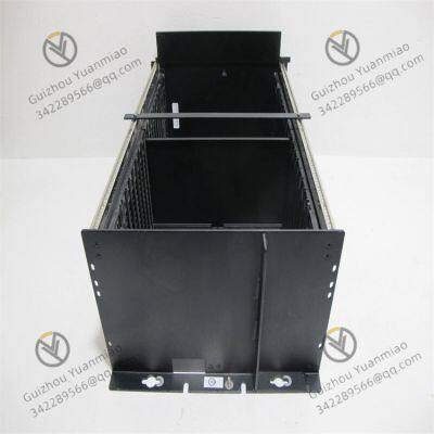
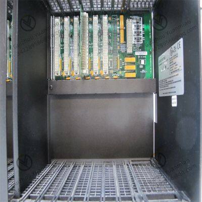
GE IC697CHS770 Dual-redundant rear-mounted rack module
Core Design Concept
Detailed Hardware ArchitectureDual CPU DesignRedundant Backplane SystemDual Power SupplyRedundant Connection of I/O ModulesSoftware Synchronization MechanismData MirroringHeartbeat DetectionDisturbance-Free Switching AlgorithmFault Handling ProcessFault DetectionSwitch TriggeringFault RecoveryApplication AdvantagesHigh ReliabilitySimplified MaintenanceCompatibilityTypical Application ScenariosConfiguration RecommendationsSummary
Core Design Concept
Detailed Hardware ArchitectureDual CPU DesignRedundant Backplane SystemDual Power SupplyRedundant Connection of I/O Modules
Software Synchronization MechanismData MirroringHeartbeat DetectionDisturbance-Free Switching AlgorithmFault Handling ProcessFault DetectionSwitch TriggeringFault RecoveryApplication AdvantagesHigh ReliabilitySimplified MaintenanceCompatibilityTypical Application ScenariosConfiguration RecommendationsSummary
Send Inquiry to This Supplier

* Email
Want the best price?
Post an RFQ now!

1Yr
Business Type
Trading Company
Year Established
2014
Factory Size
1,000-3,000 square meters
Product Certifications
SA8000
You May Also Like
-
GE IC697CMM731 High-speed Counting ModuleNegotiableMOQ: 1 Piece
-
GE IC697CMM741 Ethernet Communication ModuleNegotiableMOQ: 1 Piece
-
IC697CMM742-LL GE High Performance Communication ModuleNegotiableMOQ: 1 Piece
-
IC698CPE020-JX GE High Performance Processor ModuleNegotiableMOQ: 1 Piece
-
IC698CPE020-JX GE Programmable Logic Controller (PLC) ModuleNegotiableMOQ: 1 Piece
-
GE IC697CPM914 GMR Redundant CPU ModuleNegotiableMOQ: 1 Piece
-
IC754VSI12CTD GE 12 Inch Color Touch ScreenNegotiableMOQ: 1 Piece
-
GE IC697CPM915 High-performance CPU ModuleNegotiableMOQ: 1 Piece
-
IS200DSPXH1DBC GE Digital Signal Processor Control BoardNegotiableMOQ: 1 Piece
-
IS200DSPXH1DBD GE Digital Signal Processor ModuleNegotiableMOQ: 1 Piece


