Material
Other, Global universal model
Condition
Other, Global universal model
Task
Other, Global universal model
Mathematical Model
Other, Global universal model
Signal
Other, Global universal model
Customized
Non-Customized
Structure
Other, Global universal model
Dimensions
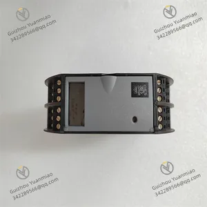
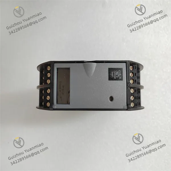
200mm x 100mm x 50mm
Operating Voltage
18V to 32V DC
Weight
Approximately 1.2kg
Functional Features
Multi-channel Signal Processing: Supports multiple digital and analog input/output channels, enabling simultaneous processing of various signal types to meet complex control requirements.
High-precision Acquisition: Provides high-resolution data acquisition with 16-bit analog input resolution and an accuracy of 0.01V or 0.01mA, ensuring high precision and real-time performance of the control system.
Modular Design: Adopts a compact module design for easy installation, expansion, and maintenance. Users can flexibly configure the module according to actual needs, suitable for various industrial application scenarios.
Strong Environmental Adaptability: Industrial-grade design with anti-vibration, anti-shock, high temperature resistance, and electromagnetic interference immunity. The protection level can reach IP67 or IP68, suitable for harsh environments.
Flexible Communication Interfaces: Supports multiple standard communication protocols and interfaces such as RS422, CAN Bus, and Ethernet, facilitating integration into existing systems.
Technical Parameters
Dimensions: 200mm x 100mm x 50mm.
Weight: Approximately 1.2kg.
Operating Voltage: 18V to 32V DC.
Operating Temperature Range: -40°C to +85°C.
Maximum Power Consumption: 3.5W.
Input/Output Channels: Supports multiple digital input/output channels, connectable to sensors, relays, valves, and other devices.

Working Principle
Signal Input
The module is equipped with multiple input channels that can connect to various sensors or signal sources, such as discrete switches and digital sensors. It can receive digital signals like switch quantities and convert analog signals output by sensors into digital signals through high-resolution analog-to-digital converters (ADCs). Each input channel has a specific input voltage range and current requirement, e.g., the input voltage range may be 10V to 30V DC, with an input current of 20mA per channel.
Signal Processing
The module embeds a microprocessor to process input digital signals. It can analyze, compute, and perform other operations on the signals according to preset programs or logic, such as judging the state change of switch signals or comparing and calculating the digital values after analog quantity conversion, providing a basis for subsequent output control.
Signal Output
When the microprocessor determines the need to output control signals based on input signals and preset logic, it sends signals through output channels. The output channels can connect to actuators such as relays and valves, with an output voltage range generally 0V to 24V DC and an output current of up to 500mA per channel. For example, when input signals meet specific conditions, the module can control the relay to close or open, thereby controlling the on/off of external circuits or the opening of valves.
Communication Interaction
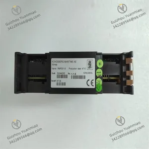
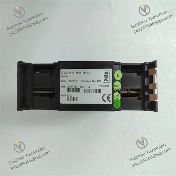
The RMP201-8 supports communication protocols like Ethernet for data interaction with other devices or systems. It can upload processed input signal data to the host computer or other control systems and receive control commands and configuration parameters from the host computer to achieve remote monitoring and parameter setting. Meanwhile, the module features advanced diagnostic functions, which can transmit its status information (such as input/output status and fault information) to users via communication interfaces for convenient monitoring and maintenance.
Status Indication and Feedback
The module is typically equipped with status indicator lights, such as "Action" and "Feedback" indicators. When the module receives commands from the controller and outputs control signals, the "Action" indicator light turns on. When external devices are triggered and transmit signals to the module, the "Feedback" indicator light turns on, and the module uploads relevant signals to the interlocking controller, enabling operators to understand the working status of the module and external devices.

Common Faults and Solutions
Communication Failure
Phenomenon: Communication interruption or abnormal data transmission between the module and other devices.
Possible Causes: Poor communication cable connection, incorrect communication parameter settings, or damaged communication interfaces.
Solutions: First, check the cable connection, re-plug or replace the cable; then verify that communication parameters match those of the connected device; if the interface is damaged, contact professionals for maintenance or module replacement.
Abnormal Input Signals
Phenomenon: Inaccurate input signal values or no response.
Possible Causes: Sensor failure, input terminal wiring issues, or module input channel failure.
Solutions: Replace faulty sensors, recheck and firmly connect input terminals. If the module input channel is confirmed to be faulty, try switching to a backup channel or repair/replace the module.
Output Control Failure
Phenomenon: Actuators do not act according to the module's output signals.
Possible Causes: Output terminal failure, abnormal load, or incorrect control parameter settings.
Solutions: First, check if the output terminals are normally powered, then inspect the load for overload or damage, and finally confirm whether the control parameter settings are correct. Re-set them if there are errors.
Module Overheating
Phenomenon: Module overheating failure may occur due to excessively high working environment temperature or poor heat dissipation.
Solutions: Ensure the module is installed in a well-ventilated location away from heat sources, regularly clean the module surface and surrounding dust, and maintain its heat dissipation space.
Parameter Setting Loss
Phenomenon: Parameter loss may be caused by prolonged module power failure, power supply abnormalities, or firmware issues.
Solutions: Re-set parameters after the module is powered on, check power supply stability, and contact the manufacturer for support if necessary for firmware upgrading or hardware inspection.