Home > Electrical & Electronics > Electrical Control System > ABB DSBB110A 57330001-Y Shield Board
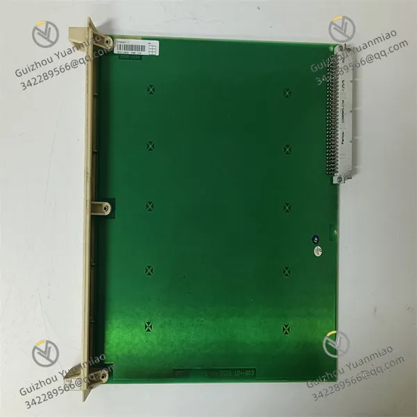
ABB DSBB110A 57330001-Y Shield Board
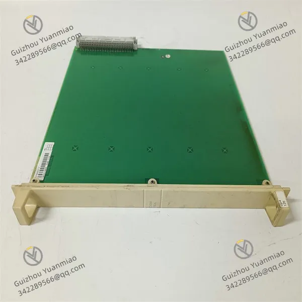
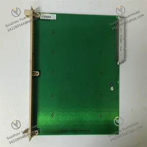
ABB DSBB110A 57330001-Y Shield Board photo-1
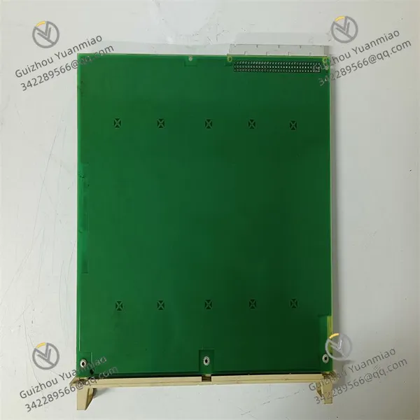
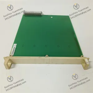
ABB DSBB110A 57330001-Y Shield Board photo-2
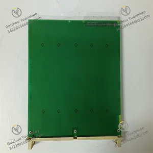
ABB DSBB110A 57330001-Y Shield Board photo-3
Negotiable MOQ: 1 Piece (Price negotiable depending on order volume and customization)
Key Specifications
Get Latest Price
Material:
Other, Global universal model
Condition:
Other, Global universal model
Task:
Other, Global universal model

Payment & Shipping
Payment Methods:
Port of Shipment:
China
Delivery Detail:
Delivery time depends on order quantity.
Material Other, Global universal model
Condition Other, Global universal model
Task Other, Global universal model
Mathematical Model Other, Global universal model
Signal Other, Global universal model
Customized Non-Customized
Structure Other, Global universal model
Power Requirements 24V DC ±10%
Dimensions 170mm × 100mm × 50mm
Weight 0.2kg
ABB DSBB110A 57330001-YI. Basic Overview
The DSBB110A is a bus interface module. The model 57330001-Y belongs to the core components of ABB's industrial automation product line. This module is mainly used to connect different communication buses (such as PROFIBUS, EtherNet/IP, etc.), realize data transmission and protocol conversion between the control system and field devices, and is suitable for complex industrial scenarios requiring multi-bus compatibility (such as large PLC systems and distributed control systems DCS).
II. Functional FeaturesBus Communication and Protocol Conversion
  • Supports multiple industrial communication protocols and can be accessed as a master or slave to different bus networks (such as PROFIBUS DP, Modbus RTU, EtherCAT, etc.).

  • Realizes data mapping and conversion between different protocols (such as converting Ethernet data into PROFIBUS format) to ensure communication compatibility between heterogeneous systems.

Data Processing and Transmission
  • High-speed data transmission capability (typical transmission rate 12Mbps, specifically depending on the protocol), supporting fast exchange of real-time control data.

  • Equipped with data caching and error checking functions (such as CRC checking) to reduce communication packet loss and data errors.

System Integration and Configuration
  • Compatible with ABB control system software (such as Control Builder M, 800xA Engineering Tool), allowing bus parameters and communication addresses to be configured through a graphical interface.

  • Supports hot-swapping, facilitating module replacement during system operation without affecting overall communication.

Industrial Environment Adaptability
  • Wide operating temperature range (such as -20°C to +60°C), adapting to harsh industrial environments.

  • Anti-electromagnetic interference design (compliant with CE, UL certifications) ensures stable operation in strongly electromagnetic interference scenarios.

DSBB110A 57330001-Y (3)

III. Performance Parameters
Parameter Category Specific Indicators
Communication Protocols Supports PROFIBUS DP, Modbus RTU, EtherNet/IP, CANopen, etc. (subject to module configuration).
Transmission Rate PROFIBUS up to 12Mbps, Ethernet 10/100Mbps, Modbus up to 115.2kbps.
Interface Types - Electrical interfaces: DB9 pins (PROFIBUS), RJ45 (Ethernet), terminal blocks (Modbus).
- Number of physical interfaces: Usually 2-4 independent bus interfaces.
Node Capacity As a master, it can connect ≥32 slave devices (specifically depending on the protocol and bus load).
Power Requirements 24V DC ±10%, power consumption about 5-8W (depending on the number of interfaces and communication load).
Protection Level The module's own protection level is IP20 (installed in the control cabinet), and higher protection requirements can be met with the cabinet.
Physical Dimensions Approximately 170mm × 100mm × 50mm (similar to Of the same kind bus modules), weight about 0.2kg.
IV. Installation MethodPre-installation Preparations
  • Hardware Environment: Suitable for ABB control cabinets or standard DIN rails, ensuring good ventilation and keeping away from strong electromagnetic sources (such as motors, transformers).

  • Tools and Accessories: Screwdrivers, anti-static wristbands, bus cables (such as PROFIBUS shielded cables), terminal resistors (for bus ends).

  • Safety Precautions: Operate with power off, wear anti-static equipment, avoid touching the module circuit board; confirm that the bus type matches the module interface.

Physical Installation Steps
  • Rack Installation (such as ABB AC 800M controller rack): Insert into the specified slot and lock with fixing clips or screws to ensure a firm contact.

  • Independent Rail Installation: Fix the DIN rail in the control cabinet, snap the module onto the rail, and lock it with clips or screws, maintaining a spacing ≥20mm for heat dissipation.

Wiring Connections
  • Power Supply Wiring: Connect to the 24V DC power supply (marked "+24V" and "GND"), use 2.5mm² cables, and pay attention to the polarity.

  • Bus Wiring:

    • PROFIBUS: Connect the bus cable through the DB9 interface, and install a 120Ω terminal resistor at the end.

    • Ethernet: Use RJ45 cables to connect to switches or controllers, ensuring good contact of the Crystal head.

    • Modbus: Connect RS485/RS232 cables through terminal blocks, paying attention to the polarity of A/B wires (RS485) or the sequence of TX/RX wires (RS232).

  • Grounding Treatment: The module grounding terminal is connected to the system grounding bus, and the bus cable shielding layer is grounded at a single end (on the control cabinet side).

DSBB110A 57330001-Y (2)

V. Debugging MethodPre-debugging Inspections
  • Hardware Inspection: Confirm that the module is installed without looseness, the wiring has no short circuits or open circuits, and measure the power supply voltage (24V DC ±10%) with a multimeter.

  • System Configuration Inspection: Add the module model (DSBB110A) in ABB control system software, and assign bus addresses and protocol parameters (such as baud rate, data bits, parity bits).

Power-on and Initialization
  • Observe the indicator lights after powering on:

    • Power Light (POWER): Steady on indicates normal power supply.

    • Communication Light (COM): Flashing indicates normal bus data transmission, while steady on or off may indicate communication failure.

    • Status Light (STATUS): Green steady on indicates normal operation, and red flashing indicates configuration errors or hardware failures.

Software Configuration and Parameter Setting
  • Configure in the control system software:

    • Bus Parameters: Set the protocol type, baud rate, slave address range (such as PROFIBUS slave addresses 1-126).

    • Data Mapping: Define the register addresses and lengths of input/output data (such as Modbus holding registers 40001-40100).

    • Fault Handling: Configure the default output value in case of communication interruption (such as maintaining the last data or outputting a safe value).

  • Download the configuration to the module and restart to make the parameters effective.

Communication Testing
  • Ping Test (Ethernet): Ping the module IP address from a computer to confirm network connectivity (packet loss rate ≤1%).

  • Data Read/Write Test: Use bus debugging tools (such as PROFIBUS Diagnostic) to read slave data or send commands through the PLC to confirm the accuracy of module reception and forwarding.

  • Realtime Test: Send periodic data (such as at 100ms intervals) and measure data transmission delay to ensure it meets control requirements (typical delay ≤5ms).

DSBB110A 57330001-Y (1)

VI. Common Faults and Handling
Fault Phenomenon Possible Causes Solutions
Communication light off Incorrect bus wiring, terminal resistor not installed Check bus cable connections, confirm terminal resistor installation; measure bus voltage (PROFIBUS typical 24V differential).
Data transmission interruption Baud rate mismatch, protocol parameter errors Reconfigure bus parameters (such as baud rate, parity bits) to ensure consistency with slave devices.
Module fault light on Hardware damage, abnormal power supply Check the power supply voltage, restart the module; if invalid, replace the module and re-download the configuration.
Slave device unresponsive Address conflict, bus overload Check whether the slave address is unique and reduce bus load (such as reducing the number of slaves or lowering the communication frequency).
VII. Application Scenarios
The DSBB110A is widely used in:
  • Process control fields: Integration of different bus devices in the chemical, petroleum, and power industries (such as interconnecting PROFIBUS instruments and Ethernet controllers).

  • Manufacturing: Communication hubs for multi-protocol devices in production lines (such as connecting Modbus frequency converters and EtherNet/IP robot systems).

  • Building automation: Protocol conversion of devices from different manufacturers in building control systems (such as connecting LonWorks sensors to BACnet networks).

  • Energy management systems: Communication integration of PLCs with smart meters and protection devices in photovoltaic power stations and substations.

VIII. Comparison with Similar Products
Module Model DSBB110A DSBC172 (Another ABB bus module)
Protocol Support PROFIBUS, Modbus, Ethernet Mainly supports CANopen, EtherCAT
Transmission Rate Up to 12Mbps (PROFIBUS) Up to 100Mbps (EtherCAT)
Number of Interfaces 2-4 independent interfaces 1-2 high-speed interfaces
Application Scenarios Multi-protocol hybrid systems High-speed real-time control (such as motion control)
Product Tags: DSBB110A , 57330001-Y , 3BSE003127R1

Send Inquiry to This Supplier

* Message
0/5000

Want the best price? Post an RFQ now!
Verified Business License
Business Type
Trading Company
Year Established
2014
Factory Size
1,000-3,000 square meters
Product Certifications
SA8000