

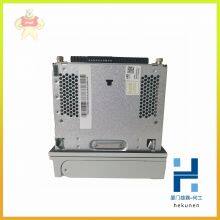
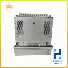
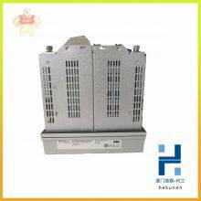
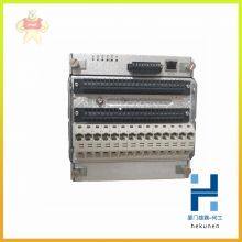
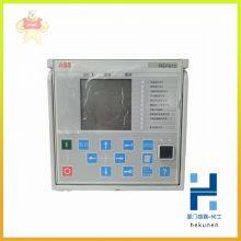
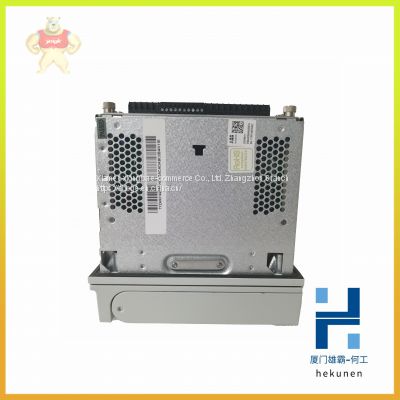
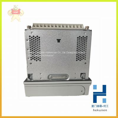
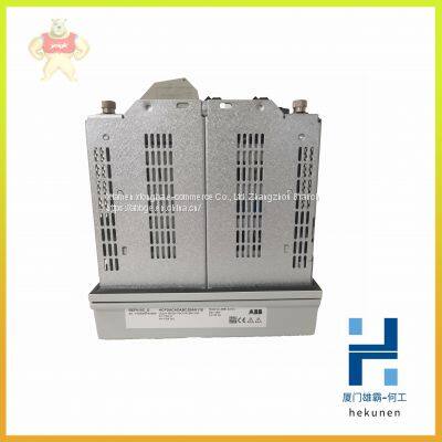
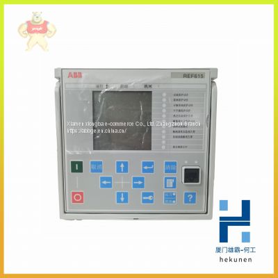
REF601 REF610 REF610C ABB Control Panel Touch Screen (in Stock)
Related Products
-
 REF610C11LCLR ABB Relay System Module (brand New)US$ 190 - 200MOQ: 100 Pounds
 -
REF615 REF615C ABB Module of Feeder Protection and Measurement and Control DeviceUS$ 100 - 200MOQ: 100 Pounds
-
REF615C-D HCFCACABANB2BAN1XD ABB New Original Protection Integrated RelayUS$ 165 - 166MOQ: 100 Pounds
-
REF615E-D Original Imported ABB Relay Protection DeviceUS$ 100 - 200MOQ: 100 Pounds
-
REF615E-E HBFAABAANAA4BNA11E ABB Safety Protection ControllerUS$ 113 - 166MOQ: 100 Pounds
REF601 REF610 REF610C ABB Control panel touch screen (in stock)
REF601 REF610 REF610C ABB Control panel touch screen (in stock)
Our Email: 2235954483@qq.com
contact number:13313705507
contacts:HE
The CI854/CI854A/CI854B is powered from the processor unit via the CEX-Bus
and requires therefore no additional external power source.
Use the following procedure to install the CI854/CI854A/CI854B/TP854:
1. Mount the unit onto the DIN-rail, see Mounting AC 800M Units onto DIN-Rail
on page 71 and Installing the PM85x/PM86x/TP830 Processor Unit in Single
Configuration on page 84.
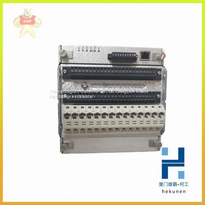
2. Install a connector on the PROFIBUS DP cable. A connector with a switchable
built-in bus termination is recommended. Connect the cable screen to the metal
case of the connector to ground the screen via CI854/CI854A/CI854B. Connect
the data cable wire A to the terminal PIN8 (RxD/TxD-N) and the data cable
wire B to the terminal PIN3 (RxD/TxD-P). If the data transfer cable has data
wires with red and green insulation, then the following assignment should be
used:
Data cable wire A: green
Data cable wire B: red
3. Connect the cable shield for both lines to functional ground, for example by
using a grounding clamp.
4. Connect the PROFIBUS DP cable to one of the connectors PROFIBUS A or
PROFIBUS B on the baseplate. For support of Line Redundancy connect a
second PROFIBUS DP cable to the other contact.
5. If the CI854/CI854A/CI854B is at the end of the PROFIBUS DP cable, switch
the bus termination ON. Otherwise leave the bus termination switched OFF.
The following applies for CI854A/CI854B:
6. If the CI854A/CI854B is installed in a redundant configuration connect the
PROFIBUS DP cable to primary and backup module. Do it like described in
Figure 44 on page 126. Switch the termination ON for the interface on primary
or backup module that is at the end of the line.

Send Inquiry to This Supplier

You May Also Like
-
RET650 RET670 ABB Microcomputer Based Transformer Protection DeviceUS$ 100 - 200MOQ: 100 Pounds
-
REX010 HESG324426R0001 HESG324389 ABB Earth Fault Protection UnitUS$ 165 - 600MOQ: 100 Pounds
-
REX521GHHPSH07G REX521GHHPSH50G ABB The Logic Controller is Brand New and OriginalUS$ 100 - 200MOQ: 100 Pounds
-
SM810K01 3BSE030928R1 ABB Ac800m Controller Communication ModuleUS$ 190 - 260MOQ: 100 Pounds
-
SM811K01 3BSE018173R1 ABB For Industrial Modular RobotsUS$ 113 - 260MOQ: 100 Pounds
-
UCD208A101 UCD224A102 ABB Compact Tension Measuring Unit (available in Stock)US$ 100 - 200MOQ: 100 Pounds
-
UCD224A103 UCD240A101 ABB High Voltage Variable Frequency Drive Board Control BoardUS$ 165 - 600MOQ: 100 Pounds
-
UDD406A 3BHE041465P201 ABB Main Unit of Field ControllerUS$ 190 - 260MOQ: 100 Pounds
-
UFC092BE01 HIEE300910R1 ABB Fieldbus Module in StockUS$ 113 - 200MOQ: 100 Pounds
-
UFC718AE01 HIEE300936R0001 ABB Unit Module ControllerUS$ 165 - 260MOQ: 100 Pounds

