Contact Platform Support
 Help Center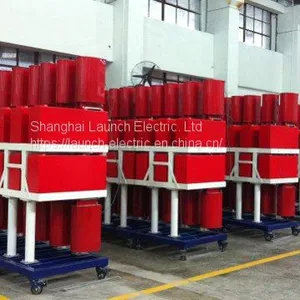




Description |
Type F impulse current generator |
|
Model |
CDLF |
|
Structure |
Type F |
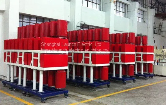
Each unit consists of 6 capacitors vertically placed on an experiment platform, with a multi-tap waveform modulating inductor being concatenated at the capacitor terminal; any multiple units are arranged in rows around the discharging ball-gap; modulate the waveform modulating inductor placed on each capacitor terminal according to the square waveform and the sample resistance during the test. |
Application |
Applicable to the long duration of impulse current withstand test of valve plates, section of an arrester and the entire arrester. |
|
Advantages |
Artistic appearance |
As shown in the figure. |
Modular design |
The charging device, the waveform modulating inductor, the capacitor rack, the discharging ball-gap etc. are designed as independent function modules, which are convenient for assembly and repair. |
|
Skillful arrangement |
Impulse current square waveforms with different energy can be generated through the combination of various units and different arrangements of capacitors of each unit. |
|
Convenient waveform modulating |
The waveform modulating inductors spread on each capacitor through multi-tap winding, which provide convenient short circuit of inductors and various combinations, so it is easy to modulate various impulse current square waveforms. |
|
Compact structure |
The discharging ball cylinder, the sample platform and measuring components are stacked and installed on the same base in order, through which a compact structure and a small inductance loop are achieved. |
|
Stable and reliable triggering |
Durable graphite pebbles are used as the discharging balls; the ball-gap transmission is controlled by a cylinder which provides stable triggering. |
|
Convenient moving |
Swivel casters are installed on each modular unit for easy and convenient moving. |
|
Stable system performance |
Long-time running at 80% of the rated current. |
|
Performance |
Current wave |
1.0 - 2.0mS and 1.0 - 1.5kA impulse current square waveform can be generated; |
2.0mS and 3.0 - 12.0kA impulse current square waveform can be generated; | ||
3.0mS and 6.0kA impulse current square waveform can be generated; | ||
4.0mS and 3.0kA impulse current square waveform can be generated; | ||
6.4mS and 3.0kA impulse current square waveform can be generated; | ||
Split-type structure is employed for the charging device and the main body of the impulse current generator. | ||
Bridge rectification is employed for the charging device. | ||
Automatic grounding and automatic switching of polarity are available in the charging device (external). | ||
The discharging ball is installed in a sealed insulating cylinder, which can decrease the discharging noise. | ||
A safety grounding device is equipped for the main capacitor. | ||
A Rogwoski coil and a capacitive residual voltage divider are used for measuring components. | ||
The technical indexes and performance of type F package equipment are at the advanced level in China. | ||
CDL Series Impulse Current Generator
– Main Specifications
Model |
Rated Current (kA) |
Waveform (μS) |
Rated Capacity (kJ) |
No. of Stages (n) |
Note |
|
CDL/C 20/5.4 |
20 |
8/20 |
5.4 |
1 |
||
CDL/ C 40/ 21.6 |
40 |
8/20 |
21.6 |
1 |
||
CDL/ C 100/ 54 |
100 |
8/20 |
4/10 |
54 |
1 |
|
CDL/ C 200/ 150 |
200 |
8/20 |
4/10 |
150 |
1 |
|
CDL/H 200/ |
50~200 |
8/20 4/10 |
30/80 1/20 |
54~250 |
2 |
Multi- waveform |
CDL/F 8/ |
1.0~8 |
2ms~ 10ms |
100~1000 |
2 |
Rectangular waveform |
|
CDL/ H 20/ 360 |
20 |
8/20 |
>7 |
360 |
12 |
For testing Complete Surge arrestors |