








 Contact Platform Support
 Help Center
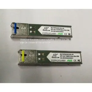
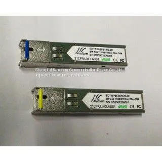
BDTRP653S1SN-20 2.5G SFP Transceiver


Related Products
The SFP-BIDI transceivers are high performance, cost effective modules supporting dual data-rate of 2.5Gbps/2.125Gbps and 20km transmission distance with SMF.
The transceiver consists of three sections: a DFB laser transmitter, a PIN photodiode
integrated with a trans-impedance preamplifier (TIA) and MCU control unit. All modules satisfy
class I laser safety requirements.
The transceivers are compatible with SFP Multi-Source Agreement (MSA) and SFF-8472.
For further information, please refer to SFP MSA.
FEATURES:
Dual data-rate of 2.5Gbps/2.125Gbps operation
1550nm DFB laser and PIN photo detector for 20km transmission
1310nm DFB laser and PIN photo detector for 20km transmission
BIDI SC/UPC type pluggable optical interface
Compliant with SFP MSA and SFF-8472 with simplex SC receptacle
RoHS compliant and lead-free
Single +3.3V power supply
Support Digital Diagnostic Monitoring interface
Case operating temperature Commercial:
0°C to +70°C
Extended: -10°C to +80°C
Industrial: -40°C to +85°C
Pin Assignment: I. Pin Descriptions Notes: 1. Circuit ground is internally isolated from chassis ground. 2. Laser output disabled on TDIS >2.0V or open, enabled on TDIS 3. Should be pulled up with 4.7k – 10 kohms on host board to a voltage between 2.0V and 3.6V. MOD_DEF(0) pulls line low to indicate module is plugged in. 4. BDTRP413L1SN-20 transceivers operate between OC-3 and OC-48, 1x and 2x Fiber Channel, and Gigabit Ethernet data rates and respective protocols without active control. BDTRP413L1SN-20 transceivers operate at 1x and 2x Fiber Channel, and Gigabit Ethernet data rates and respective protocols without active control. 5. LOS is open collector output. Should be pulled up with 4.7k – 10 kohms on host board to a voltage between 2.0V and 3.6V. Logic 0 indicates normal operation; logic 1 indicates loss of signal. II. Absolute Maximum Ratings Ⅲ. Electrical Characteristics (TOP = -40 to 85 ℃, VCC = 3.00 to 3.60 Volts) Notes: 1. Non condensing. 2. AC coupled. 3. Or open circuit. 4. Into 100 ohm differential termination. 5. 20 – 80 % 6. LOS is LVTTL. Logic 0 indicates normal operation; logic 1 indicates no signal detected. 7. All transceiver specifications are compliant with a power supply sinusoidal modulation of 20 Hz to 1.5 MHz up to specified value applied through the power supply filtering network shown on page 23 of the Small Form-factor Pluggable (SFP) Transceiver MultiSource Agreement (MSA), September 14, 2000. 8. Measured with DJ-free data input signal. In actual application, output DJ will be the sum of input DJ and DDJ. IV. Optical Characteristics (TOP = 0 to 70℃, VCC = 3.00 to 3.60 Volts) Transmitter Note (1): Measure at 2^23-1 NRZ PRBS pattern Note (2): Transmitter eye mask definition Receiver Note (1): Measured with Light source 1550nm(1310nm), ER=8.5dB; BER = Note (2): When LOS de-asserted, the RX data+/- output is signal output. V. Environmental Specifications Block Diagram of Transceiver: Mechanical Dimensions: Recommended PCB Layout: Recommended Front Panel Layout Opening for LC: Recommend Application Circuit:

Send Inquiry to This Supplier

You May Also Like
-
1550/1310 SFF Bi_directional TransceiverUS$ 100 - 150MOQ: 1 Unit
-
1550/1310 SFF Bi_directional TransceiverUS$ 100 - 150MOQ: 1 Unit
-
PON TransceiverUS$ 100 - 150MOQ: 1 Unit
-
Efficient Reliable Compact PTN Packet Transport Network DeviceUS$ 200 - 200MOQ: 1 Unit
-
Ethernet Over SDH STM-1 ConverterUS$ 200 - 200MOQ: 1 Unit
-
3 Ethernet Over SDH STM-1 ConverterUS$ 200 - 200MOQ: 1 Unit
-
Gigabit Ethernet to STM-1 ConverterUS$ 200 - 200MOQ: 1 Unit
-
Gigabit Ethernet Over STM-4 SDH ConverterUS$ 200 - 200MOQ: 1 Unit
-
Smart Cassette GPON OLT 4PONUS$ 200 - 200MOQ: 1 Unit
-
8PON EPON OLT With 10G UplinkUS$ 200 - 200MOQ: 1 Unit


