

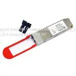
40Gb/s 40km QSFP+ Transceiver

Related Products
-
 SFP+ Direct Attach Passive Copper CablesUS$ 80 - 150MOQ: 1 Unit
 -
Hybrid Passive Copper 100GE QSFP28 to 4x 25GE SFP28US$ 80 - 150MOQ: 1 Unit
-
10G Bi-Directional SFP+ Optical TransceiverUS$ 100 - 150MOQ: 1 Unit
-
10Gb/s XFP Optical TransceiverUS$ 100 - 150MOQ: 1 Unit
-
10Gbps DWDM XFP 40KmUS$ 100 - 150MOQ: 1 Unit
The BD-OPQC40 is a transceiver module designed for 40Km optical communication applications. The design is compliant to 40GBASE-ER4 of the IEEE P802.3ba standard. The module converts 4 inputs channels(ch) of 10Gb/s electrical data to 4 CWDM optical signals, and multiplexes them into a single channel for 40Gb/s optical transmission. Reversely, on the receiver side, the module optically de-multiplexes a 40Gb/s input into 4 CWDM channels signals, and converts them to 4 channel output electrical data.
The central wavelengths of the 4 CWDM channels are 1271, 1291, 1311 and 1331 nm as members of the CWDM wavelength grid defined in ITU-T G694.2. It contains a duplex LC connector for the optical interface and a 38-pin connector for the electrical interface. To minimize the optical dispersion in the long-haul system, single-mode fiber (SMF) has to be applied in this module.
The product is designed with form factor, optical/electrical connection and digital diagnostic interface according to the QSFP Multi-Source Agreement (MSA). It has been designed to meet the harshest external operating conditions including temperature, humidity and EMI interference.
The module operates from a single +3.3V power supply and LVCMOS/LVTTL global control signals such as Module Present, Reset, Interrupt and Low Power Mode are available with the modules. A 2-wire serial interface is available to send and receive more complex control signals and to obtain digital diagnostic information. Individual channels can be addressed and unused channels can be shut down for maximum design flexibility.
This product converts the 4-channel 10Gb/s electrical input data into CWDM optical signals (light),
by a driven 4-wavelength Distributed Feedback Laser (DFB) array. The light is combined by the
MUX parts as a 40Gb/s data, propagating out of the transmitter module from the SMF. The receiver
module accepts the 40Gb/s CWDM optical signals input, and de-multiplexes it into 4 individual
10Gb/s channels with different wavelength. Each wavelength light is collected by a discrete avalanche photodiode (APD), and then outputted as electric data after amplified first by a TIA and then by a post amplifier.
The BD-OPQC40 is designed with form factor, optical/electrical connection and digital diagnostic interface according to the QSFP Multi-Source Agreement (MSA). It has been designed to meet the harshest external operating conditions including temperature, humidity and EMI interference. The module offers very high functionality and feature integration, accessible via a two-wire serial interface.
Features:
4 CWDM lanes MUX/DEMUX design
Up to 11.2Gbps per channel bandwidth
Aggregate bandwidth of > 40Gbps
Duplex LC connector
Compliant with 40G Ethernet IEEE802.3ba and 40GBASE-ER4 Standard
QSFP MSA compliant
Up to 40km transmission
Compliant with QDR/DDR Infiniband data rates
Single +3.3V power supply operating
Built-in digital diagnostic functions
Temperature range 0°C to 70°C
RoHS Compliant
Absolute Maximum Ratings l Recommended Operating Environment: Electrical Characteristics (TOP = 0 to 70 °C, VCC = 3.135 to 3.465 Volts) Note: 20~80% Optical Characteristics (TOP = 0 to 70°C, VCC = 3.135 to 3.465 Volts) Note: 12dB Reflection Diagnostic Monitoring Interface Digital diagnostics monitoring function is available on all QSFP+ LR4. A 2-wire serial interface provides user to contact with module. The structure of the memory is shown in flowing. The memory space is arranged into a lower, single page, address space of 128 bytes and multiple upper address space pages. This structure permits timely access to addresses in the lower page, such as Interrupt Flags and Monitors. Less time critical time entries, such as serial ID information and threshold settings, are available with the Page Select function. The interface address used is A0xh and is mainly used for time critical data like interrupt handling in order to enable a one-time-read for all data related to an interrupt situation. After an interrupt, IntL has been asserted, the host can read out the flag field to determine the affected channel and type of flag. Lower Memory Map (A0h)

Send Inquiry to This Supplier

You May Also Like
-
10Gbps DWDM XFP 80KMUS$ 100 - 150MOQ: 1 Unit
-
10G XFP BIDI TransceiverUS$ 100 - 150MOQ: 1 Unit
-
CWDM 10G XFP Optical ModuleUS$ 100 - 150MOQ: 1 Unit
-
BDTRP653S1SN-20 2.5G SFP TransceiverUS$ 100 - 150MOQ: 1 Unit
-
EPON GPON ONU Stick SFP Module With MAC InsideUS$ 100 - 150MOQ: 1 Unit
-
EPON OLT OPTICAL SFP MODULEUS$ 100 - 150MOQ: 1 Unit
-
GPON SFP OLT TransceiverUS$ 100 - 150MOQ: 1 Unit
-
1.25G Fiber Optical TransceiverUS$ 100 - 150MOQ: 1 Unit
-
1X9 WDM Optical TransceiverUS$ 100 - 150MOQ: 1 Unit
-
1550/1310 SFF Bi_directional TransceiverUS$ 100 - 150MOQ: 1 Unit


