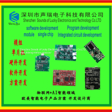
Adjustment methods of common electronic schemes
The whole machine debugging steps of the electronic scheme should be clearly and carefully specified in the debugging process documents, so that the operator can easily understand and implement. There are many kinds of electronic schemes and complex circuits. The types, requirements and technical indexes of internal unit circuits are also different, and the adjustment procedures are also different. However, in the general electronic scheme, the general process of adjustment includes the appearance inspection of the whole machine, structural adjustment, power supply adjustment, consumption test of the whole machine, adjustment of the whole machine, and test of the technical indicators of the whole machine.
1. Appearance inspection of the whole machine. The test items vary with product types and requirements, and the specific requirements can be carried out according to the process guidance card. The general electronic scheme mainly checks the shell appearance, foreign matters inside the machine, function switch, screw fastening, button or button and other items.
2. Structural adjustment. The electronic scheme is a mechatronics product. The purpose of structural adjustment is to check the firmness and reliability of the whole machine assembly. The specific contents include: the connection between each unit circuit board, components and the whole unit, whether the connection is firm, whether there is looseness, whether the adjusting device is flexible, whether the plug and socket are in good contact, etc.
3. Adjust the power supply. Check and confirm that the switch of the product power supply system (such as power circuit) is in the off position, check whether the power transfer switch meets the requirements, whether the fuse is installed, and whether the input voltage is correct. Then plug in the plug of the power switch, turn off the power switch and power on.
After starting the machine, the power indicator light will be on. At this time, you should pay attention to whether the indicator light is on, whether there is discharge, ignition, smoke, abnormal smell and other phenomena. If there are these phenomena, immediately cut off the power for inspection. In addition, it is necessary to check whether all kinds of safety switches and control systems work, and whether various cooling systems work normally.
Power debugging is usually carried out under no-load state, and the initial adjustment is carried out after all loads of the power supply are cut off. Its purpose is to avoid that the power supply circuit does not adjust the load, and some electronic components are easy to be damaged. During debugging, turn on the power supply of the power supply circuit board, measure whether there is stable DC voltage output, whether the value meets the design requirements, or adjust the sampling potentiometer to reach the rated value. Test the DC working point and voltage waveform of the detection point, check whether the working state is normal, whether there is self-excited vibration, etc.
After the no-load commissioning is normal, the power load shall be adjusted carefully. When the initial adjustment is normal, add the rated load, measure each performance index, and observe whether it meets the design requirements. When the required optimal value is reached, lock the relevant adjusting parts (such as potentiometer) to make the power circuit have the best functional state required by the load.
4. Power consumption test of the whole machine. Power consumption test is an important technical index of electronic scheme. During the test, the voltage regulator is usually used to supply the rated power voltage of the whole machine and measure the AC current in normal operation. The product of the two needs the power consumption of the whole machine. If the test value deviates from the design requirements, it indicates that there is a fault in the machine, and the whole machine should be inspected comprehensively.
5. Adjustment of the whole machine. After the unit circuit is assembled into the whole unit, its performance parameters are affected to varying degrees. Therefore, after the assembly of the whole unit, the unit substrate should be adjusted to ensure that the function of each unit substrate meets the requirements of the whole unit performance index.
6. Test of the whole technical index. Test the technical index of the whole machine which has been debugged to judge whether it has reached the technical level required by the design. There are different test methods for different types of machines. If necessary, record test data, analyze test results and write debugging report.
In the adjustment process, contact with a variety of test equipment and power supply, these equipment and test equipment often have high voltage circuit, high voltage large capacity capacitor and MOS circuit, etc. In order to protect the personal safety of adjustment personnel and avoid the damage of test instruments and components, the safety operation regulations must be strictly observed. The safety measures in debugging mainly include the safety of test environment, power supply equipment, test equipment and operation safety. The experience and methods of electronic scheme adjustment are summed up as circuit block isolation, DC post AC, attention to man-machine safety and correct use of equipment.

Send Inquiry to This Supplier
You May Also Like
-
Bluetooth Module Singlechip Development and Design of PCBAUS$ 30 - 100MOQ: 10000 Pieces
-
Bluetooth Module Singlechip Program DevelopmentUS$ 30 - 100MOQ: 10000 Pieces
-
Singlechip Bluetooth Module Voice Module Hardware Development Internet of Things SensorUS$ 30 - 100MOQ: 10000 Pieces
-
Bluetooth Module Singlechip Voice Module Noise Reduction Earphone SchemeUS$ 30 - 100MOQ: 10000 Pieces
-
Singlechip Software Development Intelligent Positioning SchemeUS$ 30 - 100MOQ: 10000 Pieces
-
Bluetooth Module Singlechip Voice Modulesoftware Development Hardware DevelopmentUS$ 30 - 100MOQ: 10000 Pieces
-
Singlechip Bluetooth Module Intelligent Wearable Hardware DevelopmentUS$ 30 - 100MOQ: 10000 Pieces
-
Singlechip Internet of Things WiFi Module Wireless ModuleUS$ 30 - 100MOQ: 10000 Pieces
-
Circuit Board Program Induction Circuit Sensor ModuleUS$ 30 - 100MOQ: 10000 Pieces
-
IC,APPLE,Qualcomm,SMIC,HUAWEI,modular,Program DevelopmentNegotiableMOQ: 5000 Pieces


