

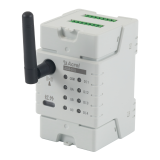
Acrel ADW400 Power Monitoring Module

Related Products
-
 Acrel ADW400 LoRa Wireless Power MeterNegotiableMOQ: 1 Piece
 -
Acrel ADW400 Multi Channel Energy MeterNegotiableMOQ: 1 Piece
-
Acrel ADW400 Wireless Multi Loop Energy MeterNegotiableMOQ: 1 Piece
-
Acrel ADW400 Wireless Multi Circuit Energy MeterNegotiableMOQ: 1 Piece
-
Acrel ADW400 Wireless Multi Circuit Power MeterNegotiableMOQ: 1 Piece
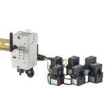
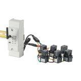
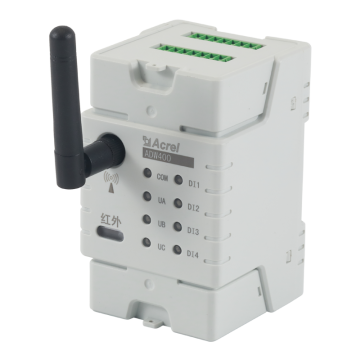
ADW400 power monitoring module is mainly used to measure three-phase active power of low-voltage network. At the same time, it can select the current input of the largest four loops. It has RS485 communication and 470MHz wireless communication functions, which is convenient for users to monitor, collect and manage electricity. It can be flexibly installed in the distribution box to realize the measurement, statistics and analysis of individual electric energy in different regions and loads.
Naming rules for ADW400 main module
Naming rules for mutual inductor
Model and specification
Electrical performance
Electrical performance
Working environment conditions
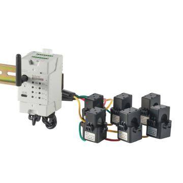
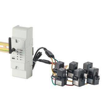
Outline dimensions and installation instructions
Installing description
Installation mode of puncture clip
Installation notes:
1.During the installation of puncture clip, it should be avoided to break it by force;
2.After the installation of the puncture clamp, let the equipment side run full load for more than 1 hour, and measure the temperature of the cable at the installation point, which should not exceed 80℃.
wiring explain
The terminal is shown in the following figure,the current signal lines of A,B and C transformers are respective connected to IA(input),IA*(output);IB(input),IB*(output)and IC(input),IB(output);A, B and C three-phase voltage signal lines are respective connected to UA, UB and UC terminals ;N is connected to UN terminals.
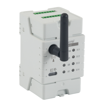
Operation and Display
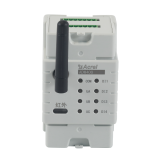
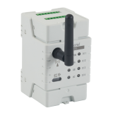
There are eight LED lights on the front of the front of the casing.They are:“DI1”,“DI2”,“DI3”,“DI4”,“UA”,“UB”,“UC”,“COM”.
When external switching input is available,“DI1”,“DI2”,“DI3”,“DI4”four lights on
When there is an external voltage input,“UA”,“UB”,“UC”three lights on.
COM has indicator flashing, when the red light flickers, indicating that the instrument carries out "LORA" communication, when the green light flickers, indicating that the instrument carries out RS485 communication.
Communication protocol
The instrument adopts MODBUS-RTU protocol or DL/645 protocol. For specific protocol formats, please refer to the relevant protocol standards.
Troubleshooting of Common Faults
The instrument does not turn on after installation, or a voltage indicator does not turn on.
Instrument wireless communication failure
Please connect the instrument RS485 interface with USB to 485 serial port first, read the parameters in the table through communication, confirm whether the parameters in the table are the same as the wireless configuration of the upper main station (channel and spread spectrum factor). If different, please modify the wireless parameters of the instrument to be consistent with the main station before re-testing; if the same, it may be the instrument and the main station phase. If the distance is too far or the interference is serious, we can try to use the external sucker antenna, or consider adding a new wireless main station nearby, and then test it.

Send Inquiry to This Supplier

You May Also Like
-
Acrel ADW400 Wireless Multi Loop Power MeterNegotiableMOQ: 1 Piece
-
Acrel ADW400 Multi Channel Power MeterNegotiableMOQ: 1 Piece
-
Acrel ADW400 Wireless Power MeterNegotiableMOQ: 1 Piece
-
Acrel ADW400 Wireless Energy MeterNegotiableMOQ: 1 Piece
-
Battery Bicycle Charging Pile Swipe Card Scan Qr Code Coin Cloud PlatformNegotiableMOQ: 1 Piece
-
Battery Bike Charging Pile Swipe Card Scan Qr Code Coin Cloud PlatformNegotiableMOQ: 1 Piece
-
Battery Bike Charging Pile Swipe Card Scan Qr Code Coin Cloud PlatformNegotiableMOQ: 1 Piece
-
Battery Bike Charging Pile Swipe Card Scan Code Coin Cloud PlatformNegotiableMOQ: 1 Piece
-
Battery Electrical Bicycle Charging Pile Swipe Card Scan Qr Code Coin Cloud PlatformNegotiableMOQ: 1 Piece
-
Battery Electrical Bike Charging Pile Swipe Card Scan Qr Code Coin Cloud PlatformNegotiableMOQ: 1 Piece


