

YD9100 Eddy Current Rotation Speed Sensor
Related Products
-
 YD69 Reverse Rotation Speed SensorUS$ 150.00 - 200.00MOQ: 1 Piece
 -
YD60 Passive Magneto-electric Speed SensorUS$ 100.00 - 140.00MOQ: 1 Piece
-
YD62 Hall Effect Rotation Speed SensorUS$ 100.00 - 140.00MOQ: 1 Piece
-
YD69 CW/CCW Measurement Speed SensorUS$ 100.00 - 110.00MOQ: 1 Piece
-
YD69 CW/CCW Dual-channel SensorUS$ 100.00 - 140.00MOQ: 1 Piece
YD9100 Eddy Current Rotation Speed Sensor
Brief Introduction
YD9100 series eddy current speed sensor is a new speed sensor .It was made in accordance with the principle of eddy
current effects. Since the vortex .Measurement method has a very wide dynamic range and a strong measurement signal.
So eddy current speed sensor has the following excellent characteristics than the magnetic-electric speed sensor :
1. It can measure 0 ~ 600,000RPM speed range. But magnetic speed sensor at low speed when the signal is weak and
can not be measured. Usually in the turning machine magnetoelectric speed sensor can't detect the machine speed.
2, The internal eddy current speed sensor have no magnetic element, so its less susceptible to external electromagnetic
interference. But magnetic speed transmission internal magnetic sensor components susceptible to external electromagnetic
interference, usually magnetic speed sensor is still in the machine stops 50Hz frequency pulses.
3, Eddy current speed sensor installation gap have wide range, easy installation and adjustment . But magnetic speed sensor mounting gap is small, installation and adjustment difficulties, and because the installation of small distances, easily
measuring surface wear.
4, The internal eddy current speed sensor has been designed and reliable pulse converter circuit, pulse shape norms,
amplitude and constant .It can and universal frequency counter or speed measuring instrument connected directly.But
magnetic speed sensor output pulse subject enlarge shaping to measure.
5, The interior design of the sensor wiring errors and short circuit protection, any wiring error does not damage the sensor.
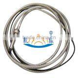
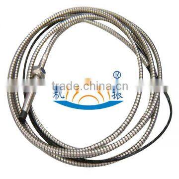
6, The sensor uses M16 × 1 stainless steel threaded Park tube packaging machinery installation size is consistent with
magnetic speed sensors, signal cable protection hose made of stainless steel, solid structure, moisture, dust, corrosion
resistance, long-term continuous operation in harsh environments.
Based on these excellent characteristics, eddy current speed sensor has been widely used in electric power, chemical
industry, metallurgy, machinery, textile industry, replacing magnetic speed sensors, to achieve the machine's speed
measurement, control and protection. Measured surface is a single phase slots or boss, you can provide a pulse of
mechanical vibration phase analysis. In addition, the sensor can be used with or close to its metal parts and switch
the alarm signal, or counting them.
Work Principle
By high-frequency oscillator, detector amplifiers, pulse conversion circuit, fault protection circuit, an oscillator using a
dedicated precision leveled IC, which produces an alternating magnetic field near the surface eddy current metal
object, which in turn affect the eddy current field oscillator amplitude, making the oscillator with the measured amplitude
decreases near metal objects by detecting amplified pulse signal generated by the pulse specification conversion circuit.
The main technical indicators
1, Power Supply: + 12 ~ + 30Vdc, maximum operating current 15mA;
2, The installation space: 2 ~ 4 mm;
3, Speed range: 0 ~ 600,000 RPM;
4, The pulse output: Sine wave output, a high level of about + 5V, low around 0V;
5, Analog output: 1 ~ 5V;
6, Housing thread: M16 × 1;
7, Shell length: 100 mm (can be selected within the range of 100 ~ 200mm);
8, Cable length: 3 m (can be within 1 ~ 300m range selection, you can select all cables armored with stainless steel hose protection);
9, The use of the environment: -30 ~ + 100 ℃.It can be soaked in oil, water and work.
Installation
YD9100 is three wires sensor (+24V ,COM ,OUT)
Red line (+24V) connects to the power;
Green line (OUT) pulse output (0~5V);
Black line (COM) connects to the ground.
When install the sensor, make it aim at the tooth crest, the installation gap is L≤1.30mm, fix it.
Warning! It is not allowed to connect the sensor output terminal (OUT) to the ground, otherwise, it will damage the sensor.
To be processed one or more grooves or convex key marker in the subject's body measurements, a groove or key tag
generates a pulse signal per revolution, using it as a speed measurement accuracy is not high. Specialized speed
measurement are generally located on a plurality of recesses or projections set key tags, or directly on the measuring
gear shaft circumference of the shaft, so that the probe can produce multiple pulses per revolution. Or the number of
gear teeth of the tag, the number of pulses per revolution of the sensor is produced, the greater the number, the more
accurate measurement. But when the high speed, due to the frequency response of the sensor limit the number of teeth
marks or gears can not be too general requirements pulse frequency must not exceed 10kHz.
Counter counts the pulses, if the counts per second of the N, or the number of gear teeth marks of the K, the Speed V is
calculated as follows:
V=60×N/K r/min (RPM)
When measured body gear, the use of a standard 60-tooth gear, its modulus should ≥2, gear width ≥8mm, non-standard gear, top width ≥2mm, teeth wide ≥4mm, tooth height ≥3mm. When measured as a single groove or convex
surface key requirement measured shaft diameter ≥20mm, the groove or key width ≥4mm, highly ≥1.5mm, length ≥10mm.
Whether gear or grooves and convex keys, the total requirement of its size can make the analog output signal generated
by the pulse amplitude is not less than 2V peak to peak, otherwise please contact us.
Installation gap 2 ~ 4mm, mounting clearance should enable the analog output voltage is within the range of 1 ~ 5V. You
can use a feeler gauge to measure the gap, if you install the sensor is powered, available multimeter to measure the analog
output voltage to adjust the gap is more convenient. Installation space is relatively good alignment sensor probe can
addendum section analog output voltage of about 3V.
When measured body gear, installation gap refers to the sensor face and being the distance between the top of the tooth.
Sensors should be installed to ensure that the width of the center line in the middle gear, and if the machine is running, it will
produce axial movement, but also taking into account the axis traverse, to ensure that the gear position sensor in the middle
of the width of the center line, especially in the gear width is small to pay attention to this point. When the test surface for a
single groove, install an integral part of coping with a gap adjustment shaft; measured surface as a single convex keys,
should be aligned with convex keys to adjust the gap. Groove or key should be parallel to the axis of the center line, and its
length as long as possible in order to prevent axial movement generated when the shaft, the probe also facing the groove
or key. In order to avoid the gap variation caused by the axial displacement of the probe and the test surface is too large,
the sensor should be mounted on the shaft radially, rather than the axial position. The groove or using a key as the speed
of the trigger member, one pulse per revolution signal which can be used as machine vibration analysis Kam-phase signal.
When the mark is a groove when installing the sensor portion of the shaft to be adjusted against the complete installation of
the gap, but not against the recess to adjust the mounting clearance. When the tag is convex button, the sensor must be i
nstalled facing convex top surface of the adjustment gap, not against other full surface of the shaft to be adjusted. Otherwise,
when the shaft is rotated, it may cause a collision with the probe projecting key, cut probe. Details of the sensor installation
instructions please refer to the Company eddy current displacement sensor for use.
Model selection instruction
YD 9100 --A--B--C--D--E--F
A: Lead Way
00: Aviation plug
01: Direct Lead
B Overall Shell length
80:80mm,
10:100,
200: 200mm
C:Unthreaded Length
20:20mm
00:00mm
D:Thread specification
01:M10*1
02:M10*1.5
03:M15*1.5
04:Special Customized
E:Length of cable
01:1m
05:5m
09:9m
F:Metal armored
00:YES
01:No

Send Inquiry to This Supplier

You May Also Like
-
SICK ICR845-2E1020 SICK Industrial Barcode Scanner for Logistics & AutomationNegotiableMOQ: 1 Piece
-
Sick WSE4S-3P3130H Order Number: 1052888 Product Family: W4S-3 Inox Hygiene Product Family: Photoelectric SensorsUS$ 100 - 200MOQ: 1 Piece
-
Pressure SensorNegotiableMOQ: 2000 Pieces
-
China NOx Sensor Nitrogen Oxygen Manufacturer Supply 12665215 12638377 12642310 12648630 12665216 12638378 For GMNegotiableMOQ: 1 Combo
-
20428461 20732304 20428462 Heavy Duty Truck Sensor Parts Fuel Tank Level Sensor For VOLVONegotiableMOQ: 1
-
King Pigeon Temperature Humidity Transducer THI100 Temperature Humidity Detector Wireless SensorUS$ 2 - 31MOQ: 5 Pieces
-
Ultrasonic Position Liquid Level Position SensorUS$ 200 - 700MOQ: 1 Piece
-
Crank Oil Seal for Toyota Auto Parts Oem 90311-95012US$ 1 - 10MOQ: 1 Piece
-
SHT10 Humidity & Temperature SensorUS$ 1 - 2MOQ: 5 Pieces
-
Wholesales & Retails HCA131A High Performance Dual Axes Tilt Sensor Switch Led Light With Tilt Switch From Shenzhen FactoryNegotiableMOQ: 1 Piece


