

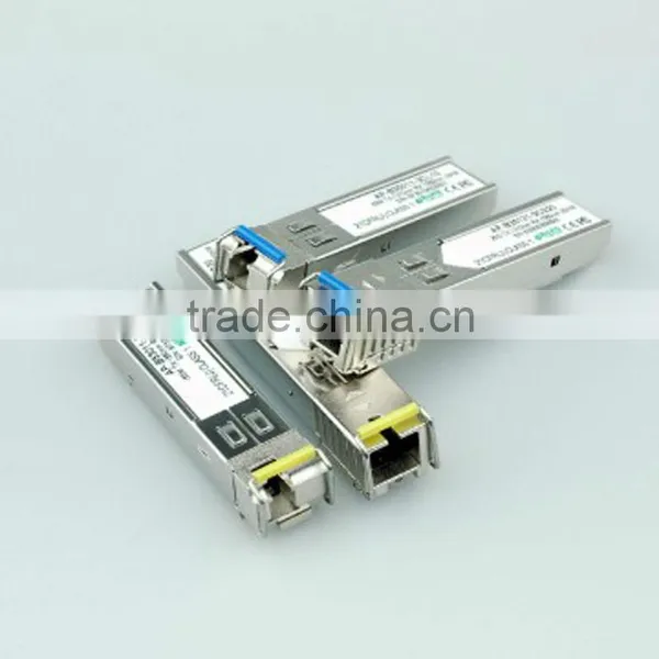
2.5G BIDI TX1310RX 1550nm 20KM SFP Transceiver

Related Products
-
 2.5G 1310nm 2Km SFP TransceiverNegotiableMOQ: 1 Piece
 -
1.25GTX1550RX1490nm80KM Single Fiber SFP TransceiverNegotiableMOQ: 1 Piece
-
1.25GTX1550RX1490nm 80KM Single Fiber SFP TransceiverNegotiableMOQ: 1 Piece
-
2.5G 1310nm 20Km SFP TransceiverNegotiableMOQ: 1 Piece
-
2.5G 1310nm 20Km SFP Transceiver With Duplex LC ConnectorNegotiableMOQ: 1 Piece
Specifications
1.1550nm 20KM SFP Transceiver2.1310nm DFB laser transmitter
3.Fiber Channel
4.Single 3.3V power supply
2.5G BIDI TX1310RX1550nm 20KM
Product Features
1.Single LC receptacle optical interface compliant
2.Hot-pluggable SFP footprint
3.1310nm DFB laser transmitter
4.RoHScompliant and Lead Free
5.Up to 20km on 9/125µm SMF
6.Metal enclosure for lower EMI
7.Single 3.3V power supply
8.Low power dissipation <700mW
9.Commercial operating temperature range: 0°C to 70°C
Applications
1.SDH STM-16 and SONET OC-48 system
2.Switch to Switch interface
3.Switched backplane applications
4.Fiber Channe
5.Router/Server interface
6.Switched backplane applications
7.Other optical transmission systems
Pin descriptions
Pin |
Symbol |
Name/Description |
Ref. |
1 |
VeeT |
Transmitter Ground (Common with Receiver Ground) |
1 |
2 |
TX Fault |
Transmitter Fault |
|
3 |
TX Disable |
Transmitter Disable. Laser output disabled on high or open. |
2 |
4 |
MOD_DEF(2) |
Module Definition 2. Data line for Serial ID. |
3 |
5 |
MOD_DEF(1) |
Module Definition 1. Clock line for Serial ID. |
3 |
6 |
MOD_DEF(0) |
Module Definition 0. Grounded within the module. |
3 |
7 |
Rate Select |
No connection required |
|
8 |
LOS |
Loss of Signal indication. Logic 0 indicates normal operation. |
4 |
9 |
VeeR |
Receiver Ground (Common with Transmitter Ground) |
1 |
10 |
VeeR |
Receiver Ground (Common with Transmitter Ground) |
1 |
11 |
VeeR |
Receiver Ground (Common with Transmitter Ground) |
1 |
12 |
RD- |
Receiver Inverted DATA out. AC Coupled |
|
13 |
RD+ |
Receiver Non-inverted DATA out. AC Coupled |
|
14 |
VeeR |
Receiver Ground (Common with Transmitter Ground) |
1 |
15 |
VccR |
Receiver Power Supply |
|
16 |
VccT |
Transmitter Power Supply |
|
17 |
VeeT |
Transmitter Ground (Common with Receiver Ground) |
1 |
18 |
TD+ |
Transmitter Non-Inverted DATA in. AC Coupled. |
|
19 |
TD- |
Transmitter Inverted DATA in. AC Coupled. |
|
20 |
VeeT |
Transmitter Ground (Common with Receiver Ground) |
1 |
Notes
1. Circuit ground is internally isolated from chassis ground.
2. Laser output disabled on TX Disable >2.0V or open, enabled on TX Disable<0.8V.
3. Should be pulled up with 4.7k - 10kohms on host board to a voltage between 2.0V and 3.6V.
MOD_DEF(0) pulls line low to indicate module is plugged in.
4. LOS is LVTTL output. Should be pulled up with 4.7k~ 10kohms on host board to a voltage between 2.0V and 3.6V. Logic 0 indicates normal operation; logic 1 indicates loss of signal.

Send Inquiry to This Supplier

You May Also Like
-
Clean Room TelephoneUS$ 140 - 160MOQ: 1 Piece
-
Hot Sale Hdpe 40/33 Pipe for Fiber Optic CableUS$ 0.63 - 0.98MOQ: 30000 Meters
-
S42024-L5101-A120-02 Control Rectifier Switch Service BoardUS$ 100 - 3,000MOQ: 1 Piece
-
FC-FC Fiber Optic Patch CordUS$ 1.12 - 2.6MOQ: 10 Pieces
-
Anritsu Site Master S331L PROMOTION PriceNegotiableMOQ: 1 Set
-
Strong Controllability 1310 Nm/1550 nm Wavelength FTTH Optical Receiver With Double WavelengthUS$ 10 - 50MOQ: 1 Set
-
Just for You Fiber Optics Light Up Paper Bag Vase, Paper Flower VaseNegotiableMOQ: 5000 Pieces
-
CYLINDRICAL MUTINATION PLUGSNegotiableMOQ: 1
-
USB AF-MINI USB 5P-B M Adapter VK2-0055NegotiableMOQ: 5000 Pieces
-
25.6V20Ah LiFePO4 for Communication DevicesNegotiableMOQ: 50 Packs


