

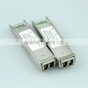
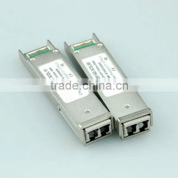
10G XFP SR 850nm Multi-rate XFP Optical Transceivers
Related Products
-
 10G XFP ZR 1550nm Multi-rate XFP Optical TransceiversNegotiableMOQ: 1 Piece
 -
10G 1550nm 40Km SFP+ 40km Optical TransceiverNegotiableMOQ: 1 Piece
-
10G DWDM SFP+ 40km Optical TransceiversNegotiableMOQ: 1 Piece
-
10G DWDM SFP+ 80km Optical TransceiversNegotiableMOQ: 1 Piece
-
10G SFP+ ER Optical TransceiversNegotiableMOQ: 1 Piece
Specifications
1.850nm sfp optical transceiver2.Hot pluggable
3. +3.3V single power supply
4. 850nm VCSEL laser
10G XFP SR 850nm Multi-rate XFP Optical Transceivers
Product Features
1. Hot pluggable
2. Support 9.95Gb/s to 11.1Gb/s bit rates
3.Below 2.5W power dissipation
4.XFP MSA package with duplex LC connector
5.Digital Diagnostic Monitor Interface
6.Very low EMI and excellent ESD protection
7.Un-cooled 850nm VCSEL laser
8. +3.3V single power supply
9.operating temperature range 0°C to 70°C
10.No reference clock requirement
Applications
1.10G BASE-ER/EW Ethernet
2.SONET OC-192/SDH STM-64
3. Other optical links
Description
10G 850nm XFP transceivers are designed for 10G Ethernet 10G BASE-ER/EW per 802.3ae and 10G SONET OC-192/SDH STM-64, and it can support data-rate from 9.953Gb/s to 11.1Gb/s.Digital diagnostics are available via I2C interface as specified in the XFP MSA.
The transceiver designs are optimized for high performance and cost effective to supply customers the best solutions for datacom and telecom applications.
Functional Diagram
Pin Definitions
1. Module ground pins GND are isolated from the module case and chassis ground within the module.
2. Open collector; Shall be pulled up with 4.7K-10Kohms to a voltage between 3.15V and 3.6V on the host board.
3. The pins are open within module.
4. Reference Clock is not required
Absolute Maximum Ratings
Electrical Characteristics(TOP=0to70°C)
Optical Characteristics(TOP=0 to 70°C,VCC3=3.13 to3.47 Volts)
Management Interface
XFP 2-wire serial interface is specified in the Chapter 4 of the XFP MSA specification. The XFP 2-wire serial interface is used for serial ID, digital diagnostics, and certain control functions. The 2-wire serial interface is mandatory for all XFP modules. The 2-wire serial interface address of the XFP module is 1010000X(A0h). In order to access to multiple modules on the same 2-wire serial bus, the XFP has a MOD_DESEL(module deselect pin). This pin (which is pull high or deselected in the module) must be held low by the host to select of interest and allow communication over 2-wire serial interface. The module must not respond to or accept 2-wire serial bus instructions unless it is selected.
XFP Management Interface
XFP Management interface is specified in the Chapter 5 of the XFP MSA specification. The Figure 1 shows the structure of the memory map. The normal 256 Byte address space is divided into lower and upper blocks of 128 Bytes. The lower block of 128 Byte is always directly available and is used for the diagnostics and control functions that must be accessed repeatedly. Multiple blocks of memories are available in the upper 128 Bytes of the address space. These are individually addressed through a table select Byte which the user enters into a location in the lower address space. The upper address space tables are used for less frequently accessed functions and control space for future standards definition.
Serial ID Memory Contents(table 01h)
Typical Interface Circuit
Package Dimension

Send Inquiry to This Supplier

You May Also Like
-
Clean Room TelephoneUS$ 140 - 160MOQ: 1 Piece
-
Hot Sale Hdpe 40/33 Pipe for Fiber Optic CableUS$ 0.63 - 0.98MOQ: 30000 Meters
-
S42024-L5101-A120-02 Control Rectifier Switch Service BoardUS$ 100 - 3,000MOQ: 1 Piece
-
FC-FC Fiber Optic Patch CordUS$ 1.12 - 2.6MOQ: 10 Pieces
-
Anritsu Site Master S331L PROMOTION PriceNegotiableMOQ: 1 Set
-
Strong Controllability 1310 Nm/1550 nm Wavelength FTTH Optical Receiver With Double WavelengthUS$ 10 - 50MOQ: 1 Set
-
Just for You Fiber Optics Light Up Paper Bag Vase, Paper Flower VaseNegotiableMOQ: 5000 Pieces
-
CYLINDRICAL MUTINATION PLUGSNegotiableMOQ: 1
-
USB AF-MINI USB 5P-B M Adapter VK2-0055NegotiableMOQ: 5000 Pieces
-
25.6V20Ah LiFePO4 for Communication DevicesNegotiableMOQ: 50 Packs


