

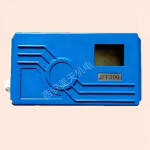
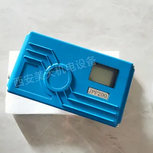
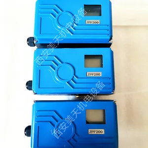
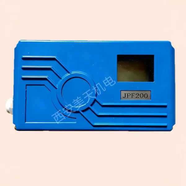
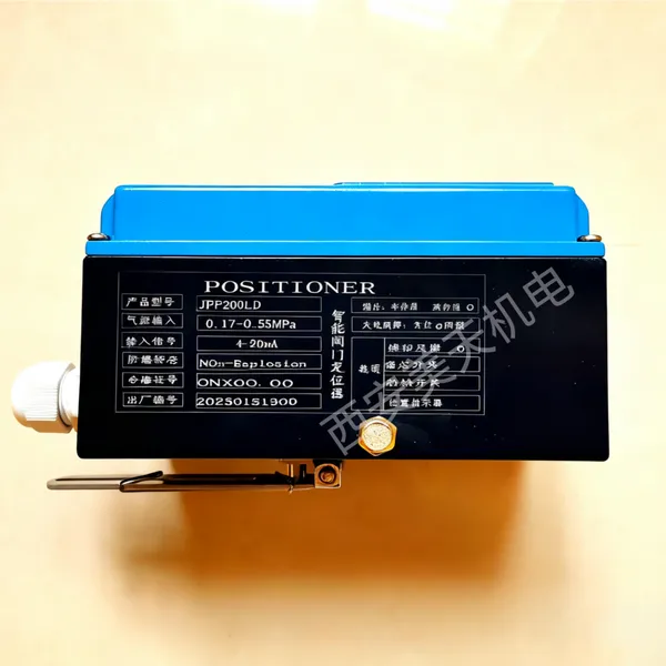
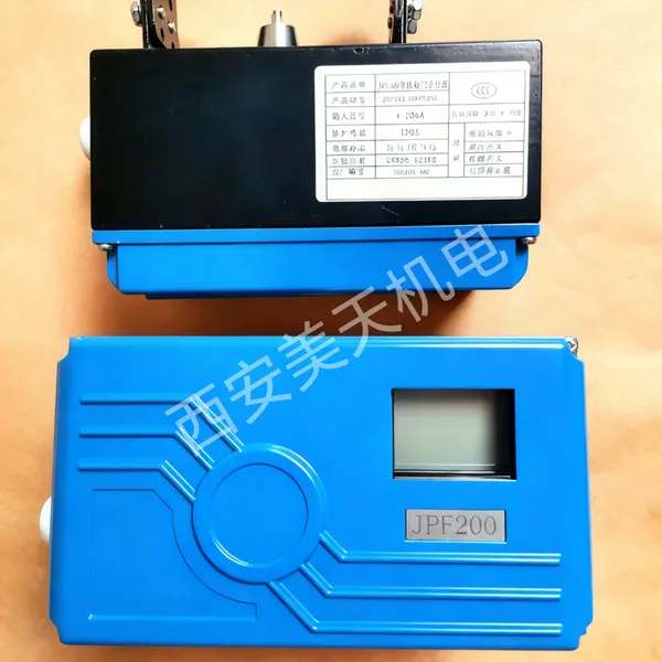
JPF200 Intelligent Electric Valve Positioner


Related Products
-
 Rotork Intelligent Valve Positioner YT-3300LDN2201SUS$ 750 - 780MOQ: 50 Units
 -
Wind Door Angle Travel Electric Actuator DKJ-5100US$ 700 - 750MOQ: 50 Units
-
Ball Hinge Mechanism QJ-160ZNegotiableMOQ: 100 Combos
-
Compact Electric Actuator Ulli-5sUS$ 110 - 115MOQ: 100 Units
-
LSDE-08 Electric ActuatorUS$ 180 - 185MOQ: 100 Units
Parameter |
JPF200 (Single-acting) |
JPF200 (Double-acting) |
Action Type |
Single-acting |
Double-acting |
Input Signal |
4-20mADC |
4-20mADC |
Minimum Current Signal |
3.0mA (Standard), 3.8mA (HART) |
3.0mA (Standard), 3.8mA (HART) |
Supply Air Pressure |
1.4-7Kgf/cm² (0.14-0.7MPa) |
1.4-7Kgf/cm² (0.14-0.7MPa) |
Stroke |
10-150mm |
0-60°, 0-90° |
Impedance |
325Ω/20mADC (Standard), 340Ω/20mADC (HART) |
325Ω/20mADC (Standard), 340Ω/20mADC (HART) |
Power Interface |
G1/2, NPT1/2 (Optional) |
G1/2, NPT1/2 (Optional) |
Air Interface |
Rc1/4, NPT1/4 (Optional) |
Rc1/4, NPT1/4 (Optional) |
Protection Class |
IP65 |
IP65 |
Explosion-proof Class |
Exia II CT6 |
Exia II CT6 |
Storage Temperature |
-40-80℃ |
-40-80℃ |
Operating Temperature |
-30-70℃ |
-30-70℃ |
Ambient Humidity |
5-95RH (at 40℃) |
5-95RH (at 40℃) |
Linearity |
±1%F.S |
±1%F.S |
Hysteresis |
±0.5%F.S |
±0.5%F.S |
Repeatability |
±0.3%F.S |
±0.3%F.S |
Output Characteristic |
Linear, Equal Percentage, Quick Opening |
Linear, Equal Percentage, Quick Opening |
Vibration Resistance |
6G |
6G |
Communication (Optional) |
HART Communication |
HART Communication |
Feedback Signal (Optional) |
4-20mA (DC24V) |
4-20mA (DC24V) |
Material |
Aluminum Alloy |
Aluminum Alloy |
Weight |
1.5Kg |
1.5Kg |
Coating |
Epoxy Polyester Electrostatic Spraying |
Epoxy Polyester Electrostatic Spraying |
Housing Color |
Black |
Black |
Category |
Code |
Description |
Remarks |
JPF2 Design sequence |
0 |
Functional form |
Standard features |
1 |
Date feedback feature |
||
2 |
HART |
||
3 |
Idle status feedback + HART |
||
Delivery stroke |
L |
Straight line |
|
R |
Arc span |
||
Action type |
S |
Single-action |
|
D |
Double-acting |
||
Protective type |
N |
Conventional type |
|
A |
Intrinsic type |
||
B |
Explosion-proof |
||
Electrical interface |
1 |
G1/2 (Optional) |
|
2 |
NPT1/2 (optional) |
||
Air interface |
1 |
Rc1/4 (Optional) |
|
2 |
NPT1/4 (optional) |
||
Installation type |
X |
Standard installation attachment (straight travel) |
|
Y |
Install the attachment (see the diagram for the shape) |
||
Z |
Angle travel installation accessories (Buyer provides size customization) |
1. The main shaft of the locator must be concentrically perpendicular to the cylinder's main shaft. The output air pipe connection must be leak-proof.
2. The display angle of the upper electric locator should be between 5° and 88.7°.
3. Press and hold the work mode key to access Menu 1, then select Straight Travel + or Angular Travel+.
4. According to the working mode, enter the menu 2 option and set the signal to 8mA.
5. Press the 3rd menu option according to the working mode, then press + and 1 to verify if the installation angle (5%-95%) is correct.
6. Press the + key to enter the 4th menu option based on the working mode. Hold the + key to enter self-adjustment. The FINISH display will appear after adjustment is complete.
7. Long press the work mode key to save and exit the industrial control system.

Send Inquiry to This Supplier


You May Also Like
-
Q941 Electric Flanged Ball ValveUS$ 185 - 217MOQ: 50 Units
-
D971F-16C Electric Flange Butterfly ValveUS$ 188 - 215MOQ: 50 Sets
-
BY-10 Electric Valve ActuatorNegotiableMOQ: 100 Units
-
Actuator Spherical Hinge Universal Joint Coupling QJ-400Z Torque 4000 Newton-metersNegotiableMOQ: 100 Sets
-
Foxboro FBM215 P0917TQ – HART Communication Output Module for Smart Valve Positioners and AO LoopsUS$ 2216.00MOQ: 1 Blade
-
Smart Valve Positioner AVP301NegotiableMOQ: 1 Piece
-
Industry Smart Valve Positioner Electro Pneumatic PositionerUS$ 1,120 - 2,200MOQ: 1 Piece
-
Japan Azbil Smart Valve Positioner AVP70 Valve Positioner TypesUS$ 500.00 - 500.00MOQ: 1 Piece
-
YTC YT-2700 Smart Valve PositionerNegotiableMOQ: 5 Pieces
-
POV Shanghai Made High Quality Smart Valve Positioner 4-20ma MotorisedUS$ 120 - 120MOQ: 1 Set


