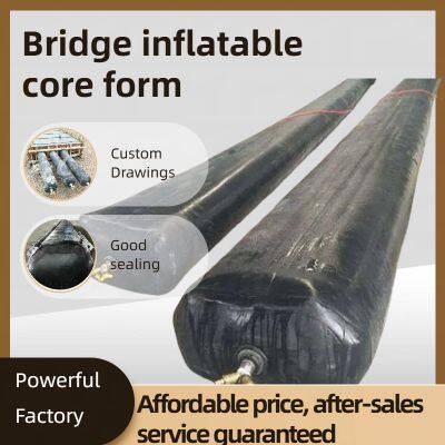
Inflatable Core Molds for Bridges: A Lightweight Solution for Hollow Concrete Components
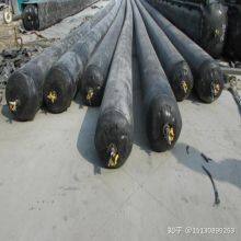
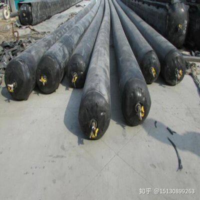
Inflatable core molds (also known as bridge inflatable bladders or pneumatic core forms) are specialized, flexible tools used in bridge construction to create hollow cavities within precast or cast-in-place concrete members. Typically made of high-elastic synthetic rubber, they replace traditional rigid core molds (e.g., steel, wood) for forming hollow sections in bridge beams, girders, and columns—reducing concrete usage, lowering structural weight, and improving construction efficiency. Below is a comprehensive introduction to their definition, structure, working principle, advantages, applications, and operational considerations.
1. Core Definition & Primary Function
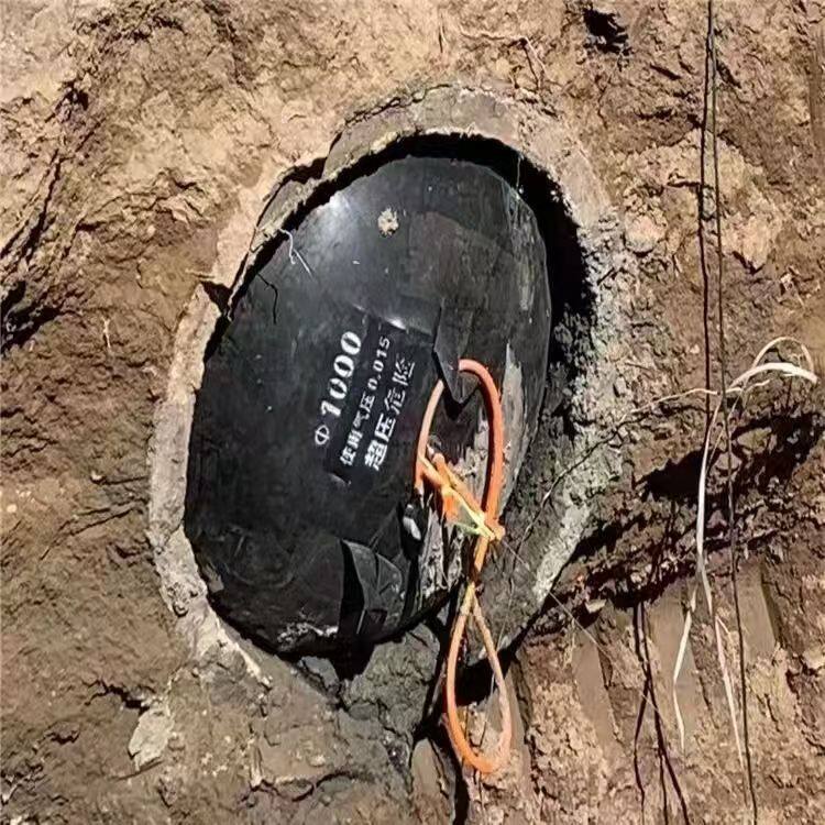
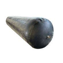
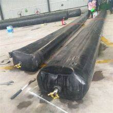
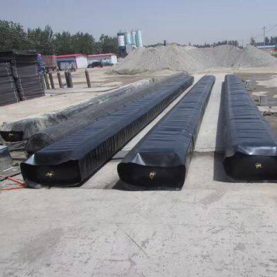
At its core, a bridge inflatable core mold is a collapsible, airtight bladder designed to occupy space during concrete pouring, then deflate and remove easily once the concrete sets. Its primary function is to:
Form hollow cavities in bridge concrete components (e.g., T-beams, box girders, hollow slabs) to reduce the member’s self-weight (by 20–40% compared to solid components) without compromising structural strength.
Ensure the inner surface of the hollow cavity is smooth and consistent, eliminating the need for secondary trimming (a common requirement with rigid core molds).
-
Adapt to complex component shapes (e.g., curved hollow sections) that are difficult or costly to achieve with rigid molds.

2. Key Structural Components
Bridge inflatable core molds are engineered for durability, airtightness, and resistance to concrete pressure. Their structure consists of four critical parts:
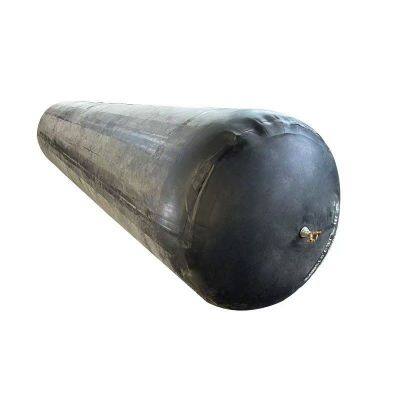
2.1 Outer Elastic Membrane
The outermost layer (the "bladder") is the core load-bearing part, made of high-performance synthetic rubber or rubber-composite materials:
Common Materials: Ethylene-Propylene-Diene Monomer (EPDM) rubber (resistant to aging, high temperatures, and concrete alkalis) or Chloroprene Rubber (CR, excellent for oil and chemical resistance).
Thickness: Typically 3–8 mm, with thicker membranes (6–8 mm) used for large-diameter cores (≥1.5m) to withstand higher concrete pressure.
-
Reinforcement: Embedded with multi-layer nylon or polyester cord fabric to enhance tensile strength (≥15 MPa) and prevent stretching or bursting during inflation.
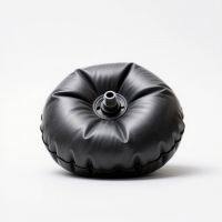
2.2 Inflation/Deflation System
This system controls the mold’s expansion and collapse, ensuring precise cavity formation:
Inflation Valve: A one-way, high-pressure valve (usually brass or stainless steel) that allows compressed air (or nitrogen) to enter. It can withstand inflation pressures of 0.15–0.3 MPa (depending on mold size and concrete thickness).
Deflation Valve: A large-diameter valve (≥20mm) for quick air release, enabling the mold to deflate and shrink within 5–15 minutes (critical for efficient demolding).
-
Pressure Gauge: A built-in or external gauge to monitor inflation pressure, preventing over-pressurization (which can damage the mold) or under-pressurization (which causes cavity deformation).
2.3 Sealing & Edge Protection
Airtight Seals: All joints (e.g., between membrane layers, around valves) are sealed with high-temperature vulcanized (HTV) rubber to ensure no air leakage—even under sustained concrete pressure (up to 0.5 MPa).
-
Edge Reinforcements: The top and bottom edges of the mold are reinforced with thickened rubber strips or metal rings to prevent tearing during installation, concrete pouring, or demolding.
2.4 Internal Support (Optional)
For extra-long or large-diameter molds (e.g., box girder cores ≥10m long), internal flexible supports (e.g., inflatable ribs or spring steel frames) are added to maintain the mold’s shape and prevent sagging during concrete pouring.
3. Working Principle
The application of inflatable core molds in bridge construction follows a simple, four-step workflow, aligned with concrete casting processes:
Step 1: Mold Preparation & Installation
Before use, inspect the mold for damage (e.g., cracks, valve leaks) and clean the outer membrane to remove dust or oil (which could affect concrete adhesion).
-
Place the deflated mold into the pre-assembled concrete formwork (e.g., the steel frame for a T-beam). Secure the mold’s edges with clamps or tape to prevent shifting during inflation or pouring.
Step 2: Inflation & Shape Setting
Connect the inflation valve to a compressed air source. Gradually inflate the mold, monitoring the pressure gauge until it reaches the design pressure (0.15–0.3 MPa).
-
After inflation, check the mold’s shape and position using a laser level or measuring tape. Adjust as needed to ensure the hollow cavity is centered and meets dimensional requirements (e.g., cavity diameter ±5mm).
Step 3: Concrete Pouring & Curing
Pour concrete into the formwork, covering the inflated mold. Use a vibrator to compact the concrete (avoid direct contact with the mold to prevent damage) and ensure no air bubbles remain around the mold.
-
Allow the concrete to cure until it reaches 70–80% of its design strength (typically 24–48 hours for normal-strength concrete). During curing, maintain the mold’s inflation pressure to prevent cavity deformation.
Step 4: Deflation & Demolding
Once the concrete is sufficiently cured, open the deflation valve to release air. The mold shrinks as air escapes, separating from the concrete’s inner surface.
-
Pull the deflated mold out of the hollow cavity (using ropes or a small winch for long molds). Clean and inspect the mold for reuse in subsequent pours.
4. Core Advantages Over Traditional Rigid Molds
Inflatable core molds outperform steel, wood, or foam core molds in bridge construction, offering six key benefits:
4.1 Lightweight & Easy Handling
-
A typical inflatable core mold (e.g., 5m long, 0.8m diameter) weighs only 20–30 kg—1/10 to 1/20 the weight of a steel mold of the same size. This eliminates the need for heavy lifting equipment (e.g., cranes) during installation and demolding, reducing labor and time costs.
4.2 Reusable & Cost-Effective
4.3 High Forming Precision
4.4 Fast Construction Cycle
-
Inflation and deflation take only minutes, and demolding is 3–5 times faster than rigid molds (which require disassembly). For precast bridge factories, this increases production capacity by 20–40% (e.g., producing 10 vs. 7 T-beams per day).
4.5 Flexibility for Complex Shapes
-
Unlike rigid molds (limited to simple cylindrical or rectangular cavities), inflatable molds can be customized to form curved, tapered, or irregular hollow sections (e.g., the curved cores in arch bridge girders). This expands design possibilities for bridge engineers.
4.6 Reduced Concrete Usage
-
By creating hollow cavities, inflatable molds cut concrete consumption by 20–40% per component. For a large bridge project (e.g., 100 T-beams), this saves hundreds of cubic meters of concrete, lowering material costs and reducing the project’s carbon footprint.
5. Typical Application Scenarios
Inflatable core molds are widely used in the construction of various bridge types, focusing on components that require hollow sections:
5.1 Precast Bridge Beams
T-Beams & I-Beams: The most common application—inflatable molds form the rectangular or circular hollow cavity in the beam’s web, reducing self-weight and improving the beam’s span capacity (e.g., enabling 20–30m spans for rural or urban bridges).
-
Box Girders: For long-span bridges (e.g., over rivers or highways), inflatable molds create multiple parallel hollow cavities in the box girder, further reducing weight while maintaining torsional stiffness.
5.2 Cast-in-Place Bridge Components
Hollow Slabs: Used in bridge decks or approach spans—inflatable molds are placed directly in the cast-in-place formwork to create lightweight hollow slabs, which are easier to transport and install than solid slabs.
-
Bridge Columns & Piers: For tall bridge columns (≥10m), inflatable molds form vertical hollow cavities, reducing the column’s weight and improving its resistance to wind and seismic loads.
5.3 Special Bridge Structures
Arch Bridges: Customized inflatable molds form the curved hollow sections in arch ribs, enabling the construction of lightweight, aesthetically pleasing arch bridges (e.g., pedestrian arch bridges in urban parks).
-
Viaducts: In high-speed railway viaducts, inflatable molds are used to create hollow girders that meet strict weight limits (to protect the railway subgrade) while ensuring structural stability.
6. Operational Precautions
To ensure safety and mold durability, follow these key guidelines during use:
6.1 Pressure Control
Never exceed the mold’s maximum inflation pressure (indicated by the manufacturer—typically 0.3 MPa). Over-pressurization can cause the membrane to burst; under-pressurization leads to cavity collapse.
-
Monitor pressure continuously during concrete pouring and curing. Temperature changes (e.g., direct sunlight heating the mold) can cause pressure fluctuations—adjust accordingly.
6.2 Installation & Positioning
Secure the mold firmly in the formwork to prevent shifting. Misalignment can result in uneven concrete thickness or mold damage during pouring.
-
Keep the mold away from sharp edges (e.g., steel formwork corners) or protruding rebars—use rubber padding to protect the membrane.
6.3 Concrete Pouring
Avoid pouring concrete too quickly (≤0.5m/h) or directing the concrete flow directly at the mold—this prevents localized pressure spikes that can tear the membrane.
-
Use a low-frequency vibrator (≤50Hz) to compact concrete, and keep the vibrator at least 100mm away from the mold.
6.4 Maintenance & Storage
After demolding, clean the mold with water and a neutral detergent (avoid harsh chemicals). Inspect for cracks, leaks, or cord fabric damage—repair small holes with rubber patches and adhesive.
-
Store the mold in a cool, dry, and shaded area (avoid direct sunlight or high temperatures, which accelerate rubber aging). Inflate it to 20% of its design pressure during long-term storage to maintain its shape.
Summary
Bridge inflatable core molds represent a cost-effective, efficient, and flexible innovation in bridge construction. By replacing rigid molds with lightweight, reusable bladders, they streamline hollow component production, reduce material usage, and expand design flexibility—making them a go-to solution for modern bridge projects, from small rural bridges to large-scale viaducts and arch bridges.