Home > Electrical & Electronics > Electrical Control System > GE DS200NATOG2ADx Analog Output Interface Sub-board

GE DS200NATOG2ADx Analog Output Interface Sub-board
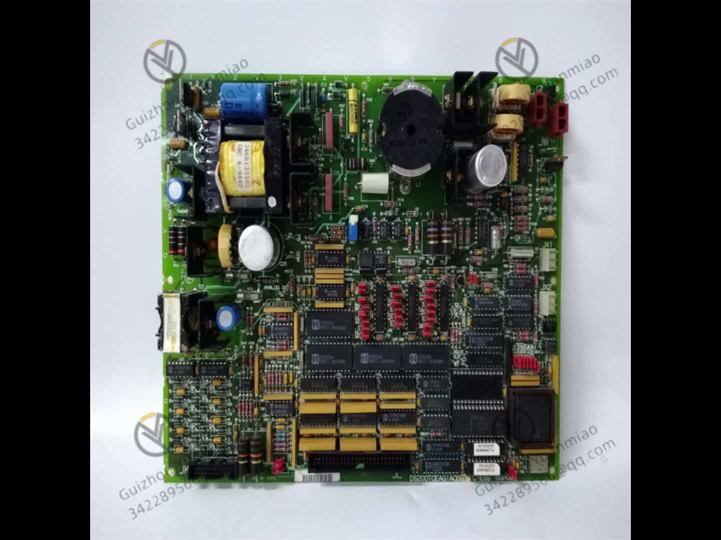
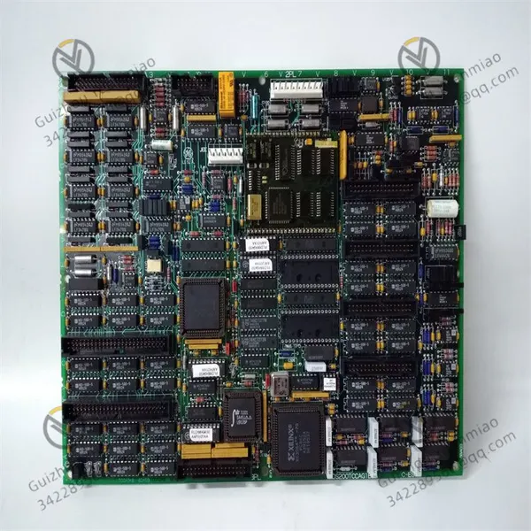
GE DS200NATOG2ADx Analog Output Interface Sub-board photo-1
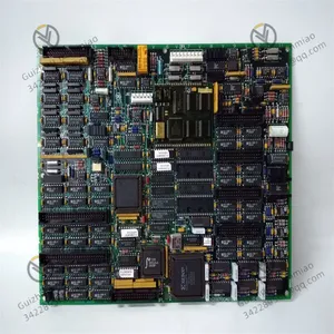
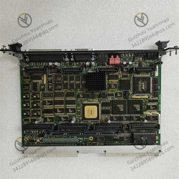
GE DS200NATOG2ADx Analog Output Interface Sub-board photo-2
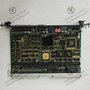
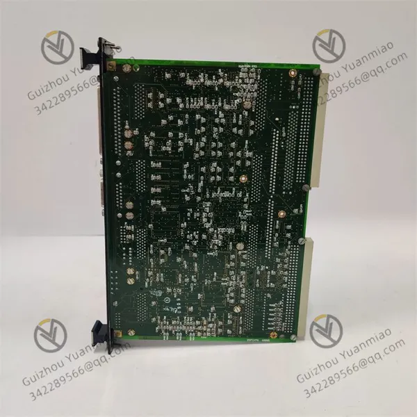
GE DS200NATOG2ADx Analog Output Interface Sub-board photo-3
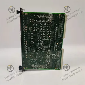
Negotiable MOQ: 1 Piece (Price negotiable depending on order volume and customization)
Key Specifications
Get Latest Price
Material:
Other
Certification:
Other
Function:
Other

Payment & Shipping
Payment Methods:
Port of Shipment:
China
Delivery Detail:
Delivery time depends on order quantity.
Material Other
Certification Other
Function Other
Condition Other
Task Other
Mathematical Model Other
Signal Other
Customized Other
Structure Other

GE  DS200NATOG2ADx  analog output interface sub-board

DS200DSPCH1ADA (1)


I. Module Positioning and Functional Overview

This module is an interface sub-board related to industrial communication or analog output, commonly used in control systems such as Mark V/VI, responsible for signal transmission, protocol conversion, or analog drive.


II. Speculation on Core Working Principles1. Hardware Architecture and Signal Processing PathInput Interface Layer

It may support multiple industrial bus protocols (such as VME, Modbus, CANopen, etc.), and receive digital signals from the main control board (such as DPSC) or external devices through dedicated connectors (such as DB25, Phoenix terminals). For example:


  • Receiving control commands from the processor (such as digital signals, register configuration data).

  • Collecting status signals from external sensors (such as switch input).

Logic Processing Layer

Built-in FPGA or CPLD programmable logic devices to parse and process input signals:


  • Protocol Conversion: Converts the parallel bus protocol of the main control board into the control logic required by the module (such as address decoding, data buffering).

  • Data Processing: Performs operations on digital signals according to configuration parameters (such as range, accuracy, output mode) (such as linear transformation, filtering).

  • Status Monitoring: Real-time detects the working status of the module (such as power supply, temperature, communication abnormalities) through the built-in self-check circuit (BIST), and feeds back through LED indicators (such as PWR, RUN, ERR).

Analog Output Drive

If the module includes analog output functions (such as "AO" characteristics), it works through the following processes:


  • Digital-to-Analog Conversion (DAC): Uses 12-bit or 16-bit DAC chips to convert processed digital signals into analog voltage/current signals (such as 0-10V, 4-20mA).

  • Signal Conditioning: Amplifies and smooths analog signals through operational amplifiers and filter circuits to suppress noise and improve driving capability (such as load resistance matching).

  • Electrical Isolation: Adopts optocoupler or magnetic coupling isolation technology to achieve electrical isolation of input/output signals (isolation voltage ≥1500Vrms) to prevent interference or lightning damage.

Communication Interface and Bus Collaboration

Communicates with the main control board (such as DS200DPSC) through a dedicated parallel bus (such as VME bus), following GE's custom protocol rules:


  • Transmitter: The module feeds back processed status data, fault codes, etc., to the main control board through the bus.

  • Receiver: The main control board sends configuration commands (such as channel enable, range setting) through the bus, and the module parses and executes corresponding operations.


DS200LDCCH1AGA (2)2. Key Technical Logic (Taking Analog Output as an Example)

Link Working Mechanism
Digital Signal Input Receives digital commands from the main control board (such as output value register data), and determines the target channel through address decoding.
DAC Conversion Converts digital values into corresponding analog quantities according to the resolution (such as 12 bits) (e.g., digital value 4095 corresponds to 10V full scale).
Signal Conditioning Eliminates high-frequency noise through a low-pass filter, and adjusts the output impedance through an operational amplifier (such as voltage mode ≥10kΩ, current mode ≤500Ω).
Isolation and Protection Optocoupler isolates input/output circuits, and TVS diodes protect ports from transient voltage surges.
Feedback and Calibration Some modules have built-in feedback resistors, sample output signals through ADC and compare them with set values to achieve automatic calibration (such as temperature drift compensation).


3. Collaborative Workflow with the SystemInitialization Phase

  • After the module is powered on, the self-check circuit detects the hardware status of the power supply, memory, DAC, etc., and displays the initialization result through LED.

  • The main control board sends configuration parameters (such as channel range, output mode) through the bus, and the module stores the parameters in EEPROM or RAM.

Operation Phase

  • Real-time receives output commands from the main control board (such as "channel 1 outputs 5V"), and drives the DAC to output corresponding analog quantities after logical processing.

  • If it is a communication module, it may be responsible for converting protocols such as Modbus and Profibus of field devices into signals recognizable by the system to achieve data forwarding.

Fault Handling Phase

  • When over-temperature, overload, or communication abnormalities are detected, the module triggers a self-protection mechanism (such as closing the output), sends fault codes to the main control board, and prompts specific problems through LED flashing (such as fast flashing of the ERR light indicating a DAC fault).


III. Common Characteristics of GE Mark Series ModulesElectrical Characteristics

  • Power supply is typically +5V DC (±5%) + ±15V DC (analog part), power consumption ≤20W, operating temperature -40°C to +70°C, compliant with industrial-grade vibration resistance (such as 2.5g@10-2000Hz) and impact standards.

Interface Design

  • Analog signals are transmitted through BNC or RJ45 interfaces, digital signals use DB25 connectors, power interfaces are Phoenix terminals, and support stackable installation with the main control board (such as fixed above DS200DPSC via positioning pins).


Product Tags: DS200NATOG2ADx

Send Inquiry to This Supplier

* Message
0/5000

Want the best price? Post an RFQ now!
Verified Business License
Business Type
Trading Company
Year Established
2014
Factory Size
1,000-3,000 square meters
Product Certifications
SA8000