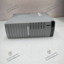
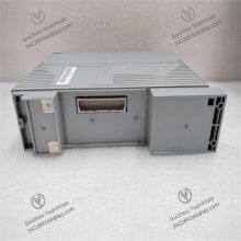
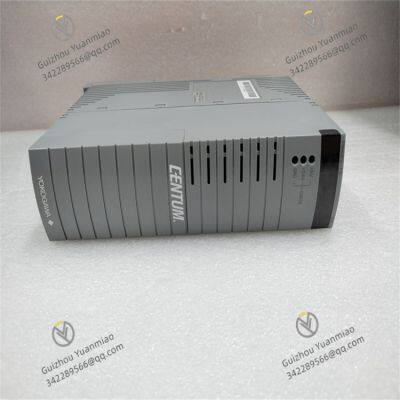
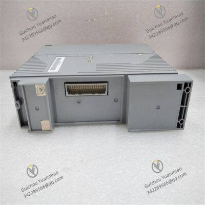
Material
Other, Global universal model
Condition
Other, Global universal model
Task
Other, Global universal model
Mathematical Model
Other, Global universal model
Signal
Other, Global universal model
Customized
Non-Customized
Structure
Other, Global universal model
Yokogawa PW482-10
Overview
The PW482-10 can be seamlessly integrated with the Distributed Control System (DCS) and Safety Instrumented System (SIS), simplifying factory automation design and improving equipment integration. It meets various system configuration requirements, including centralized and distributed setups, and can be installed in hazardous areas such as Zone 2 or Division 2.
Functional Features
High Reliability: Supports redundant configuration. The Field Control Node (FCN) autonomous controller, fieldbus modules, and control networks all feature redundancy. Hot-swapping is supported, ensuring processes do not interrupt even when damaged modules are replaced. The fault-tolerant design guarantees the continuity of critical processes.
Seamless Integration: Enables seamless connection with Yokogawa DCS and SIS systems. Using a single process network saves engineering design time, while integrated information display is clearer and more practical. Common control and network architecture standards reduce maintenance costs and optimize factory operations.
Long-life Design: The aluminum electrolytic capacitors inside the power module have a long replacement cycle under suitable ambient temperatures. For example, in environments below 40°C, the replacement cycle for the 220V AC specification is 8 years.

Technical Parameters
Working Principle
The PW482-10 power module processes the input 220V AC through internal rectification circuits to convert it into DC, filters out noise via filtering circuits, and stabilizes the voltage through voltage regulation circuits. It then outputs stable DC power to supply other modules, instruments, and devices in the control system, ensuring the stable operation of the entire control system.
Common Faults and Solutions
Abnormal Output Voltage: May be caused by internal voltage regulation circuit failures or unstable input voltage. First, check if the input voltage is within the rated range. If the input is normal, it may indicate internal circuit issues, requiring professional inspection and, if necessary, module replacement.
Module Overheating: May result from poor ventilation in the installation environment or excessive load. Ensure the module is installed in a well-ventilated area without obstructions, and check if the connected load exceeds the module's rated capacity. If the load is too high, adjust the load or increase the number of power modules.
Power Indicator Not Lit: May be due to poor power cable connection, blown fuse, or damaged internal power circuit. First, check if the power cable is properly connected and the fuse is intact. If both are normal, it may indicate internal module faults, requiring professional repair or replacement.

Yokogawa PW482-10 Power Module Redundancy Configuration
1. Hardware Architecture DesignDual-module Parallel Operation Mode
Two PW482-10 modules are connected in parallel via dedicated redundant cables or terminals, sharing the input power supply (220V AC) and simultaneously outputting DC power to the load. During normal operation, the two modules can distribute power according to load requirements (e.g., each Undertake 50% of the load) or be configured with the main module supplying power and the standby module in hot standby.
Redundancy Control Circuit
The module integrates a redundancy control chip internally, which real-time monitors the output voltage, current, and fault status of itself and the other module, and automatically switches the primary and standby roles through logical judgment.
2. Redundancy Switching LogicAutomatic Switching Trigger Conditions
The output voltage of the main module is lower than the rated value (e.g., ≤90% of the nominal voltage).
Internal overheating, short circuit, or component failure in the main module.
Abnormal input power supply to the main module (e.g., power outage, voltage fluctuation beyond the range).
Switching Time
The redundancy switching process is typically completed within milliseconds, ensuring that the power supply to load devices (such as DCS controllers and I/O modules) is not interrupted and avoiding data loss or control anomalies caused by power fluctuations.
3. Hot-swapping and Fault IsolationHot-swapping Support
In a redundant configuration, a single faulty module can be directly removed and replaced without cutting off the total system power. The module is designed with an anti-reverse connection protection circuit to ensure that the replacement process does not pose risks to the system or personnel.
Fault Isolation Mechanism
When a module experiences faults such as a short circuit, the redundancy circuit immediately cuts off the output of the faulty module to prevent the fault from spreading to the other module or the load side.