

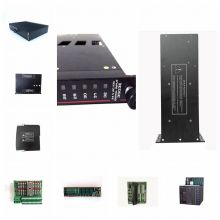
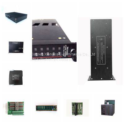
Related Products
-
 TRICONEX 9662-610 Base Plate Terminal ModuleNegotiableMOQ: 1 Piece
 -
TRICONEX 9662-810 Analog Input Module of Invensys Triangle ComponentNegotiableMOQ: 1 Piece
-
TRICONEX 9662-910 Control Card Module Water Circulation Control MachineNegotiableMOQ: 1 Piece
-
TRICONEX 9668-110 SIS System Spare PartsNegotiableMOQ: 1 Piece
-
TRICONEX 9671-810 Digital Input Terminal BoardNegotiableMOQ: 1 Piece
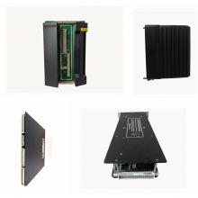
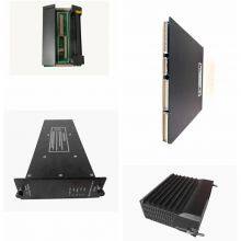
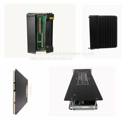
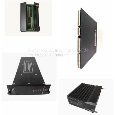
TRICONEX 9661-610
TRICONEX 9661-610
TRICONEX 9661-610
Comparison of image IDs captured by TRICONEX 9661-610 with stored IDs
The TRICONEX 9661-610 button is directly connected to the A0 (registration), A1 (deletion), A2 (upper), A3 (lower) of Arduino relative to ground, and the yellow LED is connected to the digital pin D7 of Arduino relative to ground through a 1k resistor. The Rx and Tx of the fingerprint module are directly connected to the serial pins D2 and D3 (software serial) of Arduino. The 5V power supply is used to power the fingerprint module taken from the Arduino board. The buzzer is also connected to pin A5. A 16x2 LCD4 bit mode is configured in which RS, EN, D4, D5, D6, and D7 are directly connected to the digital pins D13, D12, D11, D10, D9, and D8 of Arduino.

Send Inquiry to This Supplier


You May Also Like
-
TRICONEX 9753-110 Invensys Pulse Input Terminal BoardNegotiableMOQ: 1 Piece
-
TRICONEX 9753-1XX Invensys SIS Module Redundancy SystemNegotiableMOQ: 1 Piece
-
TRICONEX 9760-210 Redundant System Russian EnergyNegotiableMOQ: 1 Piece
-
TRICONEX 9761-210 Triconex SystemNegotiableMOQ: 1 Piece
-
TRICONEX 9765-210 SIS System Spare PartsNegotiableMOQ: 1 Piece
-
TRICONEX 9769x Invensys Security System ModuleNegotiableMOQ: 1 Piece
-
TRICONEX 9771-210 Analog Input Terminal BoardNegotiableMOQ: 1 Piece
-
TRICONEX 9771-220 Analog Input Wiring TerminalNegotiableMOQ: 1 Piece
-
TRICONEX 9853-610 Module CardNegotiableMOQ: 1 Piece
-
TRICONEX AI2351 Invensys Control System Communication ModuleNegotiableMOQ: 1 Piece


