

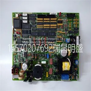
Module Spare Parts DS200TCEAG1BNE DS215TCEAG1BZZ01A

Related Products
-
 Module Spare Parts DSQC604 3HAC12928-1US$ 1 - 100000MOQ: 1 Piece
 -
Module Spare Parts DSQC679 3HAC028357-001US$ 1 - 100000MOQ: 1 Piece
-
Module Spare Parts DT602 GJR2911200R1US$ 1 - 100000MOQ: 1 Piece
-
Module Spare Parts DT680E GJR2923100R1 DT680B-EUS$ 1 - 100000MOQ: 1 Piece
-
Module Spare Parts FC-TSAI-1620MUS$ 1 - 100000MOQ: 1 Piece
Focus on DCS, PLC, robot control system and large servo system.
Main products: various modules / cards, controllers, touch screens, servo drivers.
Advantages: supply of imported original products, professional production parts,
Fast delivery, accurate delivery time,
The main brands include ABB Bailey, Ge / fuanc, Foxboro, Invensys Triconex, Bently, A-B Rockwell, Emerson, ovation, Motorola, xyvom, Honeywell, Rexroth, KUKA, Ni, Deif, Yokogawa, Woodward, Ryan, Schneider, Yaskawa, Moog, prosoft and other brands
| DS200TCEAG1BNE DS215TCEAG1BZZ01A |
The information in the following sections is important to understand A4 switch operation and installations in a stack configuration. About A4 Switch Operation in a Stack The A4 switches are stackable switches that can be adapted and scaled to help meet your network needs. These switches provide a management platform and uplink to a network backbone for a stacked group of up to eight A4 switches. Once installed in a stack, the switches behave and perform as a single switch. As such, you can start with a single switch and add more switches as your network expands. You can also mix different products in the A4H family in a single stack to provide a desired combination of port types and functions to match the requirements of individual applications. In all cases, a stack of switches performs as one large product, and is managed as a single network entity. When switches are installed and connected as described in “Connecting Stacking Cables” on page 2‐5, the following occurs during initialization: • The switch that will manage the stack is automatically established and is referred to as the manager switch. • All other switches are established as member switches in the stack. • The hierarchy of the switches that will assume the function of backup manager is also determined in case the current manager malfunctions, is powered down, or is disconnected from the stack. • The Console port on the manager switch remains active for out‐of‐band (local) switch management, but the Console port on each member switch is deactivated. This enables you to set the IP address and system password using a single Console port. Now each switch can be configured locally using only the manager’s Console port, or in‐band using a remote device and the CLI set of commands described in this section. For procedures used for various types of connections to the Console port, refer to “Connecting to the Console Port for Local Management” on page 2‐18. Once a stack is created (more than one switch is interconnected), the following occurs: 1. Switch (unit) IDs are arbitrarily assigned on a first‐come, first‐served basis. 2. Switch IDs are saved against each module. Then, every time a switch is power‐cycled, it will initialize with the same switch ID. This is important for port‐specific information (for example: fe.4.12 is the 12th Fast Ethernet port on switch number 4). 3. The management election process uses the following precedence to assign a manager switch: a. Previously assigned/elected manager switch b. Management assigned priority (values 1–15) c. Hardware preference level d. Highest MAC Addressam Gerät die Folge sein. Note: Do not install the rubber feet if you are rack mounting the switch.to a standard 19‐inch rack. Caution: To ensure proper ventilation and prevent overheating, leave a minimum clearance space of 5.1 cm (2.0 in.) at the left and right of the switch. Do not connect the switch to the AC power source until instructed to do so later in the installation process. Precaución: Para asegurar una buena ventilación y evitar que el sistema se sobrecaliente, deje un espacio mínimo de 5.1 cm (2 pulgadas) con respecto a los lados y a la parte posterior del aparato. No conecte el dipositivo a la fuente primaria hasta que no se le indique. 1 Approximately 152 cm (5 ft) from power source 3 44.5 cm (19.4 in.) for proper ventilation 2 4.45 cm (1.75 in.) per switch. (Vertical clearance depends on number of switches stacked.) 4 41.9 cm (16.5 in.) for proper ventilation

Send Inquiry to This Supplier


You May Also Like
-
Module Spare Parts FI820F 3BDH000031R1US$ 1 - 100000MOQ: 1 Piece
-
Module Spare Parts FI830F 3BDH000032R1US$ 1 - 100000MOQ: 1 Piece
-
Module Spare Parts FLN3524AUS$ 1 - 100000MOQ: 1 Piece
-
Module Spare Parts FLN4234AUS$ 1 - 100000MOQ: 1 Piece
-
Module Spare Parts FM265AUS$ 1 - 100000MOQ: 1 Piece
-
Module Spare Parts FM9925a-EUS$ 1 - 100000MOQ: 1 Piece
-
Module Spare Parts FM9925a-E HIEE451116R0001US$ 1 - 100000MOQ: 1 Piece
-
Module Spare Parts G122-824-002US$ 1 - 100000MOQ: 1 Piece
-
Module Spare Parts G408-0001US$ 1 - 100000MOQ: 1 Piece
-
Module Spare Parts GCD207B101 3BHE024642R0101US$ 1 - 100000MOQ: 1 Piece


