

Home > Auto, Motorcycle Parts & Accessories > Vehicle Repair Equipment & Tools > Diagnostic Tool > Allosun EM2292 Tractor Unit Electrical System Tester 7 PIN
Allosun EM2292 Tractor Unit Electrical System Tester 7 PIN

Negotiable
MOQ: 1 set (Price negotiable depending on order volume and customization)
Key Specifications
Get Latest Price
Business Type:
Manufacturer
Year Established:
2000
Annual Export Value:
US$50 Million - US$100 Million
Payment & Shipping
Payment Methods:
Port of Shipment:
China
Delivery Detail:
Delivery time depends on order quantity.
Related Products
-
 Allosun EM279B Tractor Unit Electrical System Tester 13 PINNegotiableMOQ: 1
 -
Allosun ES049E Wireless Machine Inspection Camera Real-time Video Display Flexible Long TubeNegotiableMOQ: 1
-
All-Sun EM272 Lambda Sensor Tester & Simulator Test 1,2,3 and 4 Wires Sensors Automotive TestNegotiableMOQ: 1
-
US Free Shipping Allosun EM6085 Digital Tire Pressure Gauge Ideal Tool for Tire Pressure TestNegotiableMOQ: 1
-
Allosun EM127 Automotive Multimeter Engine RPM Measurer Ignition System DC Volt Temp Frequency Diode Diagnosis Tester ToolNegotiableMOQ: 1
Products Description
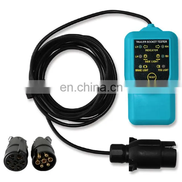
Tractor Unit Electrical System Tester
Instruction Sheet
The purpose of the tester is to test the trailer socket on the vehicle. With new
design, vehicle with a CAN-bus can also be tested. This tester is suitable only for 12V systems.
1. LED displays
When you turn on or activate a vehicle lamp, the vehicle’s wire connections for this lamp are good if the corresponding LED on the tester lights up; if the LED on the tester does not light up, the wire connections have fault.
table:The assignment of the LEDs on the tester is shown in the following
Pin Number |
Wire Color |
Wire for the following standard functions |
1 |
RED |
Left turn signal(green LED) |
2 |
WHITE |
Rear fog lamp(red LED) |
Ground |
BLACK |
If LED don't light, it may indicate problem in the ground |
4 |
GREEN |
Right turn signal (yellow LED) |
5 |
YELLOW |
Right tail light |
6 |
BROWN |
Brake lights |
7 |
BLUE |
Left tail light |
2. Connection
2.1 Insert the plug of the tester into the trailer socket on the vehicle, turn the vehicle’s power switch to the “ ON” position
but do not start the vehicle’s engine.
2.2 If the vehicle’s trailer socketis a 7-pole socket, insert the plug of the tester into the supplied adapter and then connect
the adapter to the 7-pole socket.
3. Testing the tail lamps, brake lamps and reversing lamp
3.1 To test these functions, switch on or activate the respective lamps.
If the corresponding LEDs on the tester light up, the vehicle’s wire connections for the lamps under test are good.
3.2 When the test finishes, switch off all the lamps.
4. Testing the flashers
4.1 Switch on or activate the left flasher. Then you can press the “L” end of Switch A to simulate a failure of the left flasher;
depending on the vehicle, this failure will be indicated in various ways, e.g. by a fault message on the vehicle’s instrument
panel.
4.2 Switch on or activate the right flasher. Then you can press the “R” end of Switch A to simulate a failure of the right
flasher; depending on the vehicle, this failure will be indicated in various ways, e.g. by a fault message on the vehicle’s
instrument panel.
5. Testing the hazard warning lamps
5.1 Switch on or activate the hazard warning lamps, press the “L+R” end of Switch B to simulate a failure of both flashers.
Depending on the vehicle, this failure will be indicated in various ways, e.g. by a fault message on the vehicle’s instrument
panel.
Failure identification is not possible through the flashing frequency of the flasher.
6. Testing the rear fog lamps
6.1 Switch on the rear fog lamp on the vehicle.
6.2 This light must not light up. If, nevertheless, it does, press the “54G” end of Switch B to switch it off.
7. Caution
To prevent the tester from overheating, do not press and hold down any switch of the tester for more than 15 seconds.
8. Technical data
Power Supply: 12V
Indicators: LEDs
Products Description

Send Inquiry to This Supplier

* Email
Want the best price?
Post an RFQ now!
Business Type
Manufacturer
Year Established
2000
Annual Export Value
US$50 Million - US$100 Million
Main Markets
Southern Europe, Northern Europe, Central America, Western Europe, Eastern Asia, Mid East, Oceania, Africa, Southeast Asia, Eastern Europe, South America, North America
You May Also Like
-
BYD's Dedicated Inspection Unit, VDS2100, VDCI Version 3.0.US$ 9500MOQ: 1 Box
-
TU-443 Multiple-function Oil Combustion Pressure Meter & Fuel Injection Pressure TesterNegotiableMOQ: 1
-
Brand New Great Price INJECTOR TESTING For BEIBENNegotiableMOQ: 1
-
Common Rail ValveUS$ 1 - 800MOQ: 1 Piece
-
2017 New Arrival Code Reader Diagnostic Tool WiFi ELM327 WiFi Work With IPhone and Android OBD-IIUS$ 6.8 - 6.8MOQ: 50 Pieces
-
Delivery ValveNegotiableMOQ: 6 Pieces
-
DIG01013 2016 New Car ToolUS$ 5.8 - 6.8MOQ: 5 Pieces
-
Top A1 A2 Workshop Magnetic Drill Engraving Cutting ToolsUS$ 0.6 - 1MOQ: 2000 Pieces
-
Automobile Engine ScannerUS$ 700 - 1,000MOQ: 10 Pieces
-
Mechanics Stethoscope Diagnostic Tool Cosy SpecializedUS$ 4.79 - 5.43MOQ: 1 Piece


