

Home > Manufacturing & Processing Machinery > Mould > Plastic Mould > IC200ALG322 GE Versamax Analog Output Ethernet Communication Module
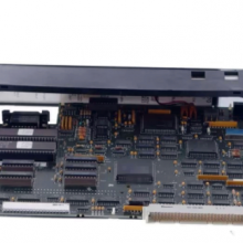
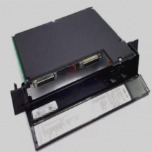
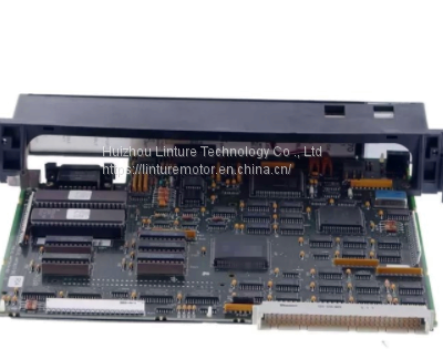
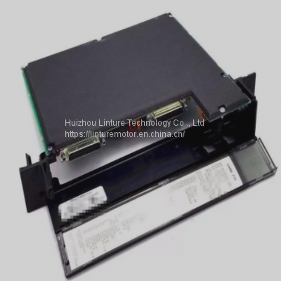
IC200ALG322 GE Versamax Analog Output Ethernet Communication Module
US$ 1 - 1000000
MOQ: 1 Unit
Key Specifications
Get Latest Price
Brand Name:
GE
Place of Origin:
United States
Model Number:
IC200ALG322
Payment & Shipping
Payment Methods:
Port of Shipment:
Bao'an international airport
Delivery Detail:
4 days
Related Products
-
 IC200MDD848 GE VersaMax Digital (Discrete) Input / Output ModuleUS$ 1 - 1000000MOQ: 1 Unit
 -
IC200MDL144 GE Module 240 VAC VersaMax Digital (Discrete) Input ModuleUS$ 1 - 1000000MOQ: 1 Unit
-
UTOPI-500UB Yaskawa Industrial Control System 1.8KW Optical EncoderUS$ 1 - 1000000MOQ: 1 Unit
-
FX1S-30MT-ESS/UL Mitsubishi Relay Output Type Brand New MoudelUS$ 1 - 1000000MOQ: 1 Unit
-
SGDS-20A05A Model Of Servopack Controller 0-55℃ Operating AmbientUS$ 1 - 1000000MOQ: 1 Unit
Brand Name
GE
Place of Origin
United States
Model Number
IC200ALG322
Product
Other, Ethernet Communication Module
Product Material
Aluminium
Shaping Mode
Die Casting
| Brand: | GE | Model: | IC200ALG322 |
|---|---|---|---|
| Origin: | USA | ||
| High Light: | ewing machine servo motor,electric servo motor | ||

Send Inquiry to This Supplier

* Email
Want the best price?
Post an RFQ now!

Business Type
Distributor/Wholesaler
Year Established
2020
Annual Export Value
Below US$1 Million
Product Certifications
ISO9001
You May Also Like
-
SGDV-180A01A Yaskawa AC Servopack Drives With Interface DriverUS$ 1 - 1000000MOQ: 1 Unit
-
SGDH-50AE Yaskawa Servo Straight Shaft With Key Servopack ModelUS$ 1 - 1000000MOQ: 1 Unit
-
SGD7S-R90A20A YASKAWA DeviceNet Module (Servo Control Power Driven Type)US$ 1 - 1000000MOQ: 1 Unit
-
1747-L543 AB SLC Processor Control Circuit Board PCB Control BoardUS$ 1 - 1000000MOQ: 1 Unit
-
ABB Robot Accessories Communication Board Card 3HNE00421-1 AC RoboticsUS$ 1 - 1000000MOQ: 1 Unit
-
PM802F ABB Controller Hybrid Plc Cpu Module Process Control SystemUS$ 1 - 1000000MOQ: 1 Unit
-
SGMJV-A5A3A-SU11 Yaskawa Small Capacity CNC Servo Motor DriverUS$ 1 - 1000000MOQ: 1 Unit
-
3HAC17328-1/01 ABB Robot AC-SERVO Ansi Grade ABB Analog Input ModuleUS$ 1 - 1000000MOQ: 1 Unit
-
SGMP-03B314B Yaskawa High Speed Industrial Electric Motor Brand NewUS$ 1 - 1000000MOQ: 1 Unit
-
SGMP-15A3A4EPU Yaskawa 200v 1500w Low Noies Electric Servo MotorsUS$ 1 - 1000000MOQ: 1 Unit


