

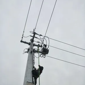
Simulated Failure Remote Controller for Overhead Line Fault Indicator
Related Products
-
 Overhead Type Fault Indicator and Wireless Communication ModuleUS$ 1 - 2MOQ: 1 Set
 -
Overhead Electric Line Fault Locator DeviceUS$ 1 - 2MOQ: 1 Set
-
Communication Fault Passage Indication System for Overhead 33KV and 11KV NetworksUS$ 1 - 2MOQ: 1 Set
-
Overhead Fault Indicator Fault Localization DeviceUS$ 1 - 2MOQ: 1 Set
-
New Type Digital Intelligent Overhead Line Type Cable Short Circuit and Ground Fault Indicator for Power Distribution Line SFIUS$ 10 - 100MOQ: 1 Piece
Remote Control PDA
OR
Description
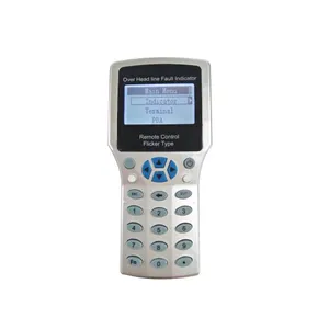
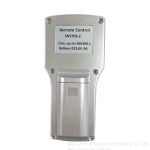
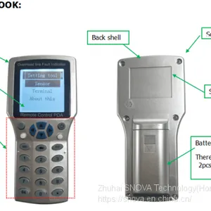
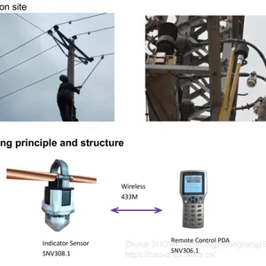
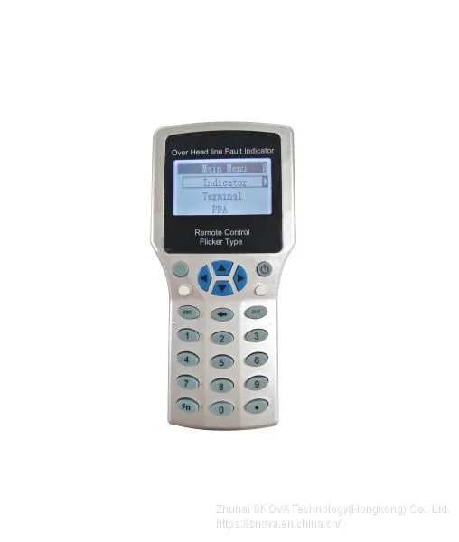
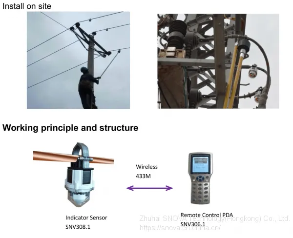
Remote Control PDA(SNV306.1) is a Tool that used for communication between user and Fault indicator(SNV308.1) and communication terminal (SNV309.1). It communicate basing on wireless 433M.
When remote Control PDA successfully connected with fault indicator, then user can read and change indicator’s parameter setting. At same time, user read indicator’s real time data, indicator battery voltage, real time current of conductor line. Etc.
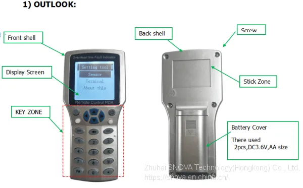
Operation instruction
1. short press “power on/off” key, Open the remote control PDA.
2. go into the “setting tool” interface.
3. On the “setting tool” interface, there are three Item:
Setting tool |
Sensor |
Terminal |
About this |
*Sensor menu: there is for operating for fault indicator
* Terminal menu: it is for operating for communication terminal
* About this: it is for operating for remote control PDA
4. How to operate: Sensor
On the “setting tool” interface, choose the “sensor” item, and press “enter key”. Then go into the a new interface, “ Sensor setting”. This interface include the below Item.
Sensor setting |
Sensor select |
Basic parameter |
Working parameter |
Online test |
Reset sensor |
*Sensor select. It is for wake up indicator sensor. and searching indicator sensor. Then choose indicator. Note: “wake up” means to open indicator sensor 433M port, make it into communication state. “search indicator” means make indicator establish communication. Only when searched indicator’s ID number, then user can operate this indicator.
*Basic parameter. It is display the indicator’s basic parameters. Tips: Please do not change it.
*Working parameter. It means indicator will use this parameter to calculate , analyze and judge fault.
*All parameter. It display all parameter of the indicator, including basic parameter and working parameter.
4.1 How to operate : sensor select
*on the “sensor setting” interface, choose the “sensor select”, then go into a new interface, “sensor select”. It include the below 3 items.
Setting select |
Wake up |
Sensor list |
Single find |
4.1.1 Wake up:
choose “wake up”, and press enter key. Then go to wake up operating.
4.1.4 How to check and operate indicator after added ID code on sensor list?

Send Inquiry to This Supplier


You May Also Like
-
Overhead Line Fault Passsage Indicator Working PrincipleUS$ 1 - 2MOQ: 1 Set
-
Overhead Electric Line Fault Locator DeviceUS$ 1 - 2MOQ: 1 Set
-
How do Overhead Line Fault Indicator FPI Work?NegotiableMOQ: 3 Pieces
-
Overhead Line Fault Passsage Indicator Working PrincipleUS$ 1 - 30MOQ: 1 Set
-
New Type Digital Intelligent Overhead Line Type Cable Short Circuit and Ground Fault Indicator for Power Distribution Line SFIUS$ 1 - 100MOQ: 20 Pieces
-
10KV-138KV Overhead Line Fault Passage Indicator With Remote ComunicationUS$ 1 - 2MOQ: 1 Set
-
China Factory Supplier Power AccessoriesUS$ 1 - 2MOQ: 1 Set
-
Fault Indicator Remote Wireless Communication TerminalUS$ 1 - 2MOQ: 1 Set
-
Control PDA for Fault LocatorUS$ 1 - 2MOQ: 1 Set
-
Remote Control PDA of Overhead Line Fault IndicatorUS$ 1 - 2MOQ: 1 Set


