

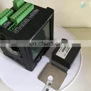
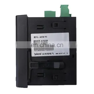
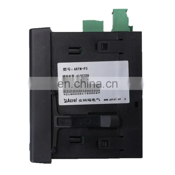
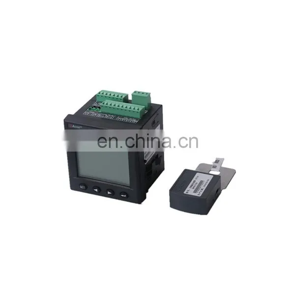
Acrel ARTM-P3 ATE100 Wireless Electrical Temperature Measuring Equipment Zigbee Wireless Transmission Device Bolt Installation


Related Products
-
 Acrel ARTM-P3 ATE200 Wireless Electrical Temperature Measuring Equipment Zigbee Wireless Transmission Device Battery InsideUS$ 280 - 280MOQ: 1 Set
 -
Acrel ARTM-P3 ATE200 Wireless Electrical Temperature Measuring Equipment Zigbee Wireless Transmission DeviceUS$ 280 - 280MOQ: 1 Set
-
ATE Series Wireless Temperature Sensor for Transformer/wireless Temperature Sensor of Circuit BreakerUS$ 42 - 45MOQ: 1 Piece
-
ATE Series Bus Bar Temperature SensorUS$ 42 - 45MOQ: 1 Piece
-
ATE Series Cable Joint Remote Temperature MonitoringUS$ 42 - 45MOQ: 1 Piece
1 Installation Guide
1.1 Product Introduction
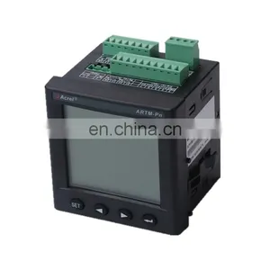
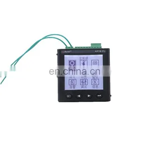
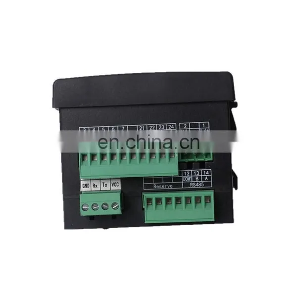
ARTM-Pn wireless temperature measuring equipment has been developed in compliance with Specification for Wireless Temperature Measuring equipment, NB/T 42086-2016. It is suitable for 3-35kV indoor switchgears, including built-in switchgears, handcart switchgears, fixed switchgears and loop-net switchgears. It is also suitable for 0.4kV low-voltage switchgears such as fixed switchgears and drawer switchgears. The wireless temperature sensors can be installed at any heating point in switchgears, the device utilizes the wireless data transmission technology for real-time transmission of monitored temperature data and displays such data on ARTM-Pn locally. In addition, it can be networked via the RS485 port for remote intelligent monitoring.
1.2 Type Introduction
1.3 Technical Features
Items |
Features |
||
Power Source |
AC85-265V,DC100-300V |
||
Power Consumption |
8W |
||
Communication |
Protocol |
Modbus-RTU |
|
Baud rate (bps) |
2400,4800,9600,19200 |
||
Environment |
Temperature |
-10℃~55℃ |
|
Humidity |
≤95% |
||
|
|
86kPa~106kPa |
||
|
MTBF
|
≥50000 h |
||
Active wireless temperature sensor |
Wireless frequency |
2.4GHz |
|
Communication distance |
10m in open area |
||
Sampling frequency |
25s |
||
Transmitting frequency |
4min |
||
Power source |
Battery |
||
Installation |
Bolted/Strap-secured |
||
Range of temperature |
-40℃~+125℃ |
||
Precision |
±2℃ |
||
Application |
Joints in high or low voltage switchgears |
||
Battery life |
≥5 years |
||
Temperature |
-20℃~+85℃ |
||
Passive wireless temperature sensor |
Wireless frequency |
470MHz |
|
Communication distance |
100m in open area |
||
Sampling frequency |
15s |
||
Transmission frequency |
15s |
||
Power source |
CT-powered, starting current≥5A |
||
Installation |
tied with cable tie |
||
Sensor probe |
Isolated |
||
Range of temperature |
0℃~+125℃ |
||
Precision |
±2℃ |
||
Application |
Joints in high or low voltage switchgears |
||
Temperature |
-20℃~+85℃ |
||
1.4 Product Installation
ARTM-Pn wireless temperature measuring equipment is installed with the front panel embedded. First, make a square hole on the switchgear surface to the specified size. Then, separate the two brackets from device and embed the device into the square hole. Finally, push and lock the brackets.
1.4.1 Installation Method
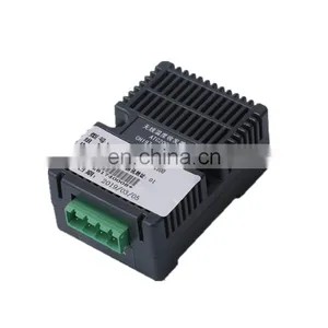
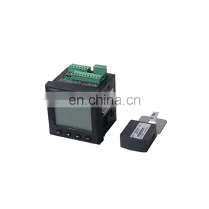
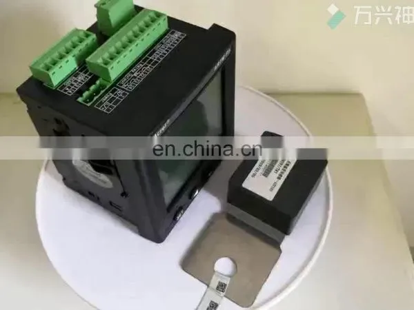
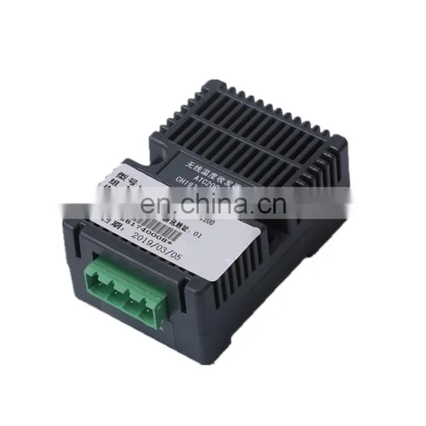
1.4.3 Wireless Temperature Coordinator Installation
The wireless temperature coordinator connected with ARTM-Pn which can be mounted on rail (DIN35mm) or bolted directly.
It can be installed in instrument chamber, circuit breaker chamber or cable chamber; the wireless temperature coordinator installation examples see images below.
1.4.4 Wireless Temperature Sensor Installation
There are three types of wireless temperature sensors and three mounting methods correspondingly, i.e. bolted type, strap-secured type and tied type.
1.4.4.1 Shape Size
1.4.4.2 Label Instruction
See images above, if the sensor is ATE100 or ATE200, the label number is same as the number on the display device, the sequence of installation is base on the label, “CH197/TA1” is first one on the phase A, and “CH197/TB1” is first one on the phase B, and so on. If the sensor is ATE300, the number behind “:” should be same as number marked in “*51809190240001*”, the sequence of installation is base on the label, “1A” is first one on the phase A, “1B” is first one on the phase B,and so on.
Notice: wireless temperature sensors and display device in the package have been matched before delivery. Do not use them with other display device or other wireless temperature sensors together. Please installing them with label on the sensor.
1.4.4.3 ATE100 Installation Method
The bolted type called ATE100 is suitable for use at joints between cable and bus bar and joints between cable and disconnector.
Bolted type temperature sensor structure introduction:
1 —— (Body of wireless temperature sensor)
2 —— (alloy baseplate, connected with temperature measuring probe)
3 —— (battery switch)
Remove the screw from the joints, and fixing the sensor on the position with the hole on the alloy baseplate, then tighten the screw, open the battery switch after all of the operation. The installation examples see images below.
1.4.4.4 ATE200 Installation Method
The strap-secured type called ATE200 is suitable for use at moving contacts and fixed contacts of breaker, cable joints and bus bar.
Strap-secured type temperature sensor structure introduction:
1 —— (Body of wireless temperature sensor, temperature measuring probe is on the other side)
2 —— (strap and hasp)
3 —— (battery switch)
Fixing the body of sensor on the position, then strapping it on the bus bar or breaker contact and frapping it through the hole on the strap, fixing the strap by hasp. Clipping the strap if it is too long when finished, if it is too short, contacting us for strap parts before installation. The installation examples see images below.
1.4.4.4 ATE300 Installation Method
The tied type called ATE300 is suitable for using at moving contacts, bus bars, cables and joints between bus bar and cable.
Tied type passive temperature sensor structure introduction:
1 —— (Body of wireless temperature sensor)
2 —— (probe, tied to temperature measuring point)
3 —— (tie, used to fix the sensor body)
4 —— (alloy chip, for CT-powered)
5—— (alloy chip hole, used to fix the alloy chip)
6 —— (tie hole, used to fix the body)
First, fixing the body of sensor on installation position with tie through the tie hole and flapping it. Then twining the alloy chip on the bus bar or breaker contact, making the alloy chip like “L” before twining it and alloy chip should be in the hole every time, twining it to 2-3 circle, and ensure its end in the alloy chip hole, clipping it if it is too long when finished, fixing the alloy chip by brown masking tape. Finally, fixing the temperature measuring probe by brown masking tape or inserting it into insulation cover. Alloy chip installation process is see images below.
The Analysis and Solvent of Some Faults
1 Power Source Fault
The LCD does not work after the device power on?
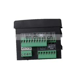
Reason: Wiring connector connects to power source wrong.
Solvent:Take off the connector of “Wireless Temp”, check up the power source connector, and power on it again.
2 Relay Output Fault
When measured wireless temperature values exceed the setting values, the relay output does not work
Reason: “Node Enable” is not “ON”.
Solvent: “MENU” -> “Para”, Set “Node Enable” to “ON”.
3 Communication Fault
PC /host computer can’t communicate with the device?
Reason: The address or other port parameter of communication is wrong.
Solvent: “MENU”->”Comm”, Set valid address or other port parameter.
4 Wireless Temperature Fault
On the “Temp” interface, the device shows “No Nodes or Nodes Fault”?
Reason: Active wireless temperature sensor battery is closed or passive wireless temperature sensor does not work, or the sensor is not matched to the device.
Solvent: (1) Check up the active wireless temperature whether its battery switch is “ON”? (When the battery switch turn to ON from OFF, the green light will lighting twice, it is worked, otherwise, wait for 5s and turn on it again); check up the circuit whether it worked with the current above 8A.
(2) Check up the bar code on wireless temperature sensor and device, if they are not same, find out the sensors with same bar code or bind the sensors online (the detailed method is at “Sensor Setting” in chapter

Send Inquiry to This Supplier


You May Also Like
-
ATE Series Cable Temperature ControllerUS$ 42 - 45MOQ: 1 Piece
-
ATE Series Cable Temperature SensorUS$ 42 - 45MOQ: 1 Piece
-
ATE Series Cable Wireless Temperature SensorUS$ 42 - 45MOQ: 1 Piece
-
ATE Series Distribution Cabinet Wireless Temperature SensorUS$ 42 - 45MOQ: 1 Piece
-
ATE Series Electrical Wireless Temperature SensorUS$ 42 - 45MOQ: 1 Piece
-
ATE Series High Voltage Wireless Temperature SensorUS$ 42 - 45MOQ: 1 Piece
-
ATE Series Low Voltage Wireless Temperature SensorUS$ 42 - 45MOQ: 1 Piece
-
Acrel ATE200 Belt Type 470mHZ Wireless Temperature Sensor for Low and Medium VoltageUS$ 41.5 - 41.5MOQ: 1 Set
-
Acrel ATE200 Motor Junction Box Wireless Temperature Measurement SensorsUS$ 41.5 - 41.5MOQ: 1 Set
-
Acrel ATE200 Wireless Temperature Monitoring Device Installed in Circuit Breaker Contacts and Bus BarUS$ 41.5 - 41.5MOQ: 1 Set


