








 Contact Platform Support
 Help Center
Home > Electrical & Electronics > Passive Components > Capacitor > RBT6 Minimum System Board STM32 Development Board STM32F103RBT6 + USB Power Cable
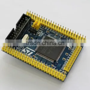
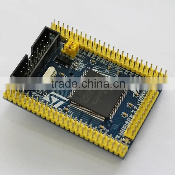
RBT6 Minimum System Board STM32 Development Board STM32F103RBT6 + USB Power Cable
US$ 7.99 - 10.99
MOQ: 1 Piece
Key Specifications
Get Latest Price
Place of Origin:
Guangdong, China
Brand Name:
STM32F103RBT6 + USB
Model Number:
STM32F103RBT6 + USB
Payment & Shipping
Payment Methods:

Port of Shipment:
SHENZHEN/HK
Delivery Detail:
Delivery time depends on order quantity.
Related Products
-
 EZ-USB FX2LP CY7C68013A USB Core Board Development Board Logic Analyzer EEPROM CY7C68013A56 ChipUS$ 6.78 - 6.99MOQ: 1 Piece
 -
AVR Mini System Development Board ISP Atmeaga16 Minimum System BoardUS$ 3.02 - 4.89MOQ: 1 Piece
-
STC Minimum Systerm Board 51 MCU SCM Development BoardUS$ 0.88 - 1.29MOQ: 1 Piece
-
Ultra-Small Size DC-DC Step Down Power Supply Module 3A Adjustable Buck Converter for Arduino Replace LM2596US$ 0.41 - 0.48MOQ: 1 Piece
-
Micro USB 5V 1A 18650 TP4056 Lithium Battery Charger Module Charging Board With Protection Dual FunctionsUS$ 0.23 - 0.46MOQ: 1 Piece
Place of Origin
Guangdong, China
Brand Name
STM32F103RBT6 + USB
Model Number
STM32F103RBT6 + USB
Note
The board has been tested already. It has been downloaded inside a led flashing program. When power supply to the board, the red light(power light) will on, three green light (debugging light) will flicker once per second.
Description
1, STM32F103RBT6 chip main parameters:
CPU frequency (M) 72
FLASH (bytes) 128KB
RAM (bytes) 20KB
Timer (pcs) 4
SPI interface (pcs) 2
IIS interface (pcs) 2
IIC interface (pcs) 2
USART interface (pcs) 3
USB interface (pcs) 1
CAN interface (pcs) 1
SDIO interface (pcs)1
ADC (channel) 16
I / O port 51
2, the standard ARM JTAG 20 PIN Simulation Interface Block (easy to connect to JLINK, ULINK2 and other mainstream emulator)
3, USB-powered, the largest provider of 800mA current .
4, support serial port 1 download. Removing the shorting cap on the figure to enter the serial ISP download.
5, 8mhz clock crystal ,and 32.768khz RTC clock oscillator.
6, all IO ports are leads, convenient for access to external circuit to do experiments.
7, the power indicator (red)
8, 3-way LED lights (green), to facilitate debugging use.
9, 3-way independent keys (black), to facilitate debugging use
10, reset: power-on reset and button reset (red)
11, leads the ISP download interface, convenient external serial small plates for ISP program download.
12, USB communication pin through a single row of pin leading, convenient for USB communication experiment (using DuPont line connection).
13, 2-way external expansion 5v power supply interface to facilitate the use of an external circuit.
14, PCB board size: 6.9cm * 5.7cm

Send Inquiry to This Supplier

Business Type
Manufacturer, Agent, Distributor/Wholesaler
Year Established
2013
Factory Size
Below 1,000 square meters
Total Employees
11 - 50 People
You May Also Like
-
Low Voltage Reactive Power Compensation Cabinet 380V-415V With Automatic Switching and ProtectionUS$ 800 - 2000MOQ: 1 Unit
-
Electronic CapacitorNegotiableMOQ: 2000 Pieces
-
6\"/8\" FramesNegotiableMOQ: 500 Pieces
-
Oven Capacitor CH85 2100VAC Capacitor for MicrowaveNegotiableMOQ: 1
-
20kA Surge Protective Device SPD (SP-D10)US$ 0.01 - 0.02MOQ: 1 Piece
-
IRFP450,100% New and Original. Top Sales!!!NegotiableMOQ: 100 Pieces
-
Miniature Capacitor 2.7v1f 6.3x9mm Super CapacitorUS$ 0.35 - 0.5MOQ: 100 Pieces
-
50V 10UF CapacitorUS$ 0.5 - 1MOQ: 200 Pieces
-
BNCHG Terminal Block Pin Connector for Over 12 Year ExperienceUS$ 0.35 - 0.4MOQ: 10000 Sets
-
Bimetal Thermal Switch 250V 5A-25ANegotiableMOQ: 1000 Pieces


