

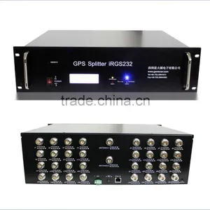
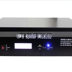
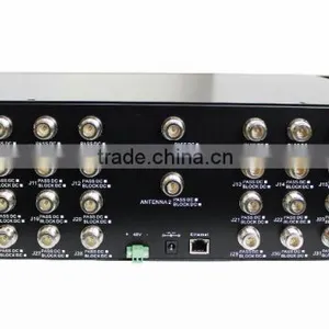
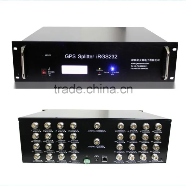
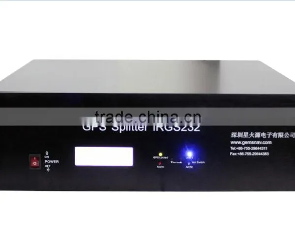
GPS Active Splitters Rackmount Dual Power GPS Splitter
Related Products
-
 GPS Active Antenna Multi-system GPS Signal Receive AntennaUS$ 1 - 580MOQ: 1 Piece
 -
GPS Power Splitter 8 Way Splitters(divider)US$ 1 - 380MOQ: 1 Piece
-
GPS Amplifier GPS Signal BoosterUS$ 1 - 385MOQ: 1 Piece
-
Power Splitter 21dB 3 Way GPS SplittersUS$ 1 - 180MOQ: 1 Piece
-
4 Way GPS SplitterUS$ 1 - 338MOQ: 1 Piece
Description
Antenna selection description
Powered hardware, the software began to calculate the signal strength of antenna 1and antenna 2,after comparing the intensity of the two input signals automatically select the high signal intensity of the antenna input. When two input antennas strength less than 34dB, according to the number of switches and the switching frequency of switching continues until the switching frequency greater than 140 times. When started with a good choice of antenna, the system continues to signal detection, when the signal strength is too low or the antenna failure, the automatic starting antenna selection logic. Holding the antenna 1 priority, it can delay the service life of the equipment.
Note: Switching times: Each antenna switch once switches the number of plus 1 time.
Switching frequency : Switch the number of times less than ten times, then switch once every minute.Switching times greater than 10 times less than 140 times , every ten minutes to switch once.Power:
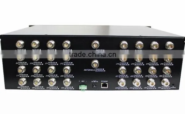
Dual power supply design, power supply 48V DC and 12V DC power supply support, to choose from, such as access to work when the 48V power supply, the 12V power supply is not access; while 48V and 12V power supply has reverse polarity protection, namely when the power is negative reversed, the device will not burn, it has a protective function.
Specifications
Electrical Specifications, Operating Temperature ‐20 to 65℃;Storage Temperature ‐30 to 80℃.
Performance Index
Install and open “GNSS signal system management terminal”software, login.
User:admin
Password:admin
Click on the "Login" sign on; "Exit" exit
2. User management
File—> User Management
3. Set IP
Set—>IP Set
4. Antenna selection and status display
In the below and to the right of the antennas selection bar for active antenna selection and state, read the "auto" selected automatically signal the better antenna access, Ant 1 is specified using the wire 1 access, ant 2 "for the specified using antenna 2 access, click the" read "read antenna can be seen when using the antenna pattern.
5. Antenna operation status display
At the top left of the interface of the software, input port status bar for the antenna operating status, real‐time displaying the access for which antenna and access antenna operation and state representation bar sketch for antenna operating status, Green said normally, red represents a short circuiting, Black said the road. If the antenna open or short circuit, the front panel of the machine GPS Locked green light is off, Alarm red lightflashes to indicate alarm, PC‐side reading antenna operating state shorted or open.
6. GPS Information
GPS information bar graph for the received satellite signal real‐time display and the right edge of the chart three options "GPS L1 only" to show only the GPS L1 satellite signal chart, "Beidou2 B1 only" to show only the compass B1 satellite signal chart, "mixed mode" for the two charts show.
GEMS RF&MICROWAVE and GEMS NAVIGATION was established in 2007, professionally designs, products and sales of coaxial microwave devices and equipment. GPS indoor coverage systems and accessories, high-power coaxial attenuators, high-power coaxial load, we accumulated many years of designing and manufacturing experience, our own designed and product of GPS indoor coverage systems and related GPS power splitter and amplifier, GPS antenna and other products widely used in microwave communications, mobile communications, high-precision measurement, power, research institutions, colleges and universities, manufacturing and other fields.

Send Inquiry to This Supplier

You May Also Like
-
Clean Room TelephoneUS$ 140 - 160MOQ: 1 Piece
-
Hot Sale Hdpe 40/33 Pipe for Fiber Optic CableUS$ 0.63 - 0.98MOQ: 30000 Meters
-
S42024-L5101-A120-02 Control Rectifier Switch Service BoardUS$ 100 - 3,000MOQ: 1 Piece
-
FC-FC Fiber Optic Patch CordUS$ 1.12 - 2.6MOQ: 10 Pieces
-
Anritsu Site Master S331L PROMOTION PriceNegotiableMOQ: 1 Set
-
Strong Controllability 1310 Nm/1550 nm Wavelength FTTH Optical Receiver With Double WavelengthUS$ 10 - 50MOQ: 1 Set
-
Just for You Fiber Optics Light Up Paper Bag Vase, Paper Flower VaseNegotiableMOQ: 5000 Pieces
-
CYLINDRICAL MUTINATION PLUGSNegotiableMOQ: 1
-
USB AF-MINI USB 5P-B M Adapter VK2-0055NegotiableMOQ: 5000 Pieces
-
25.6V20Ah LiFePO4 for Communication DevicesNegotiableMOQ: 50 Packs


