Material
Other, Global universal model
Condition
Other, Global universal model
Task
Other, Global universal model
Mathematical Model
Other, Global universal model
Signal
Other, Global universal model
Customized
Non-Customized
Structure
Other, Global universal model
Operating Temperature
-40℃~+70℃
Relative Humidity
5%~95% (non-condensing)
Dimensions
238mm × 160mm × 25.5mm
Storage Temperature
-55℃~+85℃
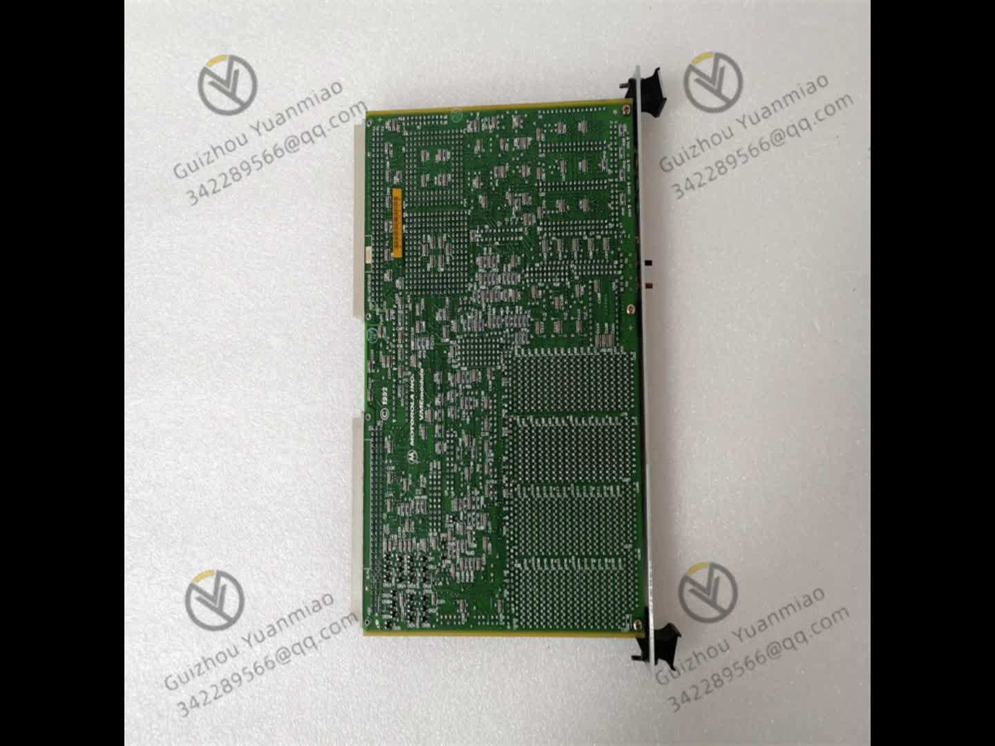
I. Overview
The MOTOROLA MVME188A is an industrial-grade VMEbus (VersaModule Eurocard bus) signal interface module launched by Motorola. As an early classic bus adaptation and signal conversion unit in the MVME series, its core positioning is "a core for signal conditioning, conversion, and VMEbus interconnection in embedded control systems under harsh industrial environments". It mainly serves fields with extremely high requirements for signal processing stability, bus compatibility, and environmental adaptability, such as power system signal acquisition, chemical equipment status monitoring, rail transit signal transmission, and upgrading of outdated industrial control systems. It undertakes the key tasks of "on-site analog/digital signal conditioning - format conversion - VMEbus data interaction - signal interconnection between devices".
With its core advantages of "industrial-grade signal processing accuracy + standardized VMEbus compatibility + wide-temperature and harsh environment-resistant design + strong adaptability to outdated systems", this module has irreplaceable value in scenarios such as upgrading outdated industrial control systems (e.g., adding bus adaptation functions to traditional sensors/actuators without VME interfaces) and multi-device signal interconnection (e.g., realizing bidirectional data interaction between different types of signal devices and VME hosts). Its core role is to solve the three major pain points in industrial control: "difficulty in heterogeneous signal compatibility", "outdated equipment without bus interfaces", and "signal distortion in complex environments". Through high-precision signal conditioning circuits, standardized VMEbus interfaces, and industrial-grade protection design, it achieves accurate acquisition of on-site weak signals (analog acquisition accuracy ≤ ±0.2% F.S.) and stable conversion (signal conversion delay ≤ 10μs), avoiding system misjudgments caused by inaccurate signal processing or bus adaptation failures (a single misjudgment may cause production process interruption or equipment misoperation), and ensuring the signal transmission reliability and bus interconnection stability of industrial control systems.
II. Technical Specifications
(1) Signal Processing and Conversion Parameters
(2) VMEbus and Interface Parameters
(3) Physical and Environmental Parameters
(4) Power Supply and Reliability Parameters

III. Functional Features
(1) Industrial-Grade Signal Processing, Ensuring Transmission Accuracy
High-Precision Signal Conditioning and Conversion
The analog channel is equipped with built-in RC filter and signal amplification circuits, which can amplify and condition on-site weak 4-20mA current signals (e.g., output from pressure sensors), suppress high-frequency interference (such as electromagnetic noise generated by frequency converters), with an acquisition accuracy of ±0.2% F.S., ensuring a signal transmission distortion rate ≤ 0.1%; The 12-bit A/D converter supports a sampling rate of 10kHz, which can quickly capture dynamic signal changes (such as voltage fluctuations in power systems), adapting to the needs of real-time monitoring scenarios.
Isolation Protection and Anti-Interference Design
Digital input/output channels adopt optocoupler isolation (isolation voltage 2500Vrms), effectively blocking ground loop interference (such as signal crosstalk caused by ground potential differences between different devices); Analog channels are equipped with common-mode rejection circuits (common-mode rejection ratio ≥ 80dB), which can still stably acquire signals in the high-electromagnetic environment of chemical workshops, avoiding fluctuations in collected data caused by interference.
(2) Standardized VMEbus Compatibility, Adapting to Multiple Systems
Seamless VMEbus Interconnection
It strictly complies with the VMEbus Rev. A specification, supports 32-bit address/data multiplexed bus, and can be directly inserted into the VME slot of MVME series VME hosts (e.g., MVME162, MVME147, etc.) without additional adapter cards, realizing high-speed data interaction with the host (bus rate 16MB/s). For example, in a power monitoring system, the voltage and current signals collected by the MVME117A can be uploaded to the MVME162 host in real-time via the VMEbus for the host to perform data analysis and control decision-making.
Multi-Module Cascading Expansion
By setting different VME addresses via hardware jumpers (supporting cascading of 4 modules), the number of signal channels can be expanded (e.g., 16-channel analog input and 32-channel digital I/O can be achieved after cascading 4 modules), adapting to multi-measurement point scenarios (such as temperature and pressure signal acquisition of multiple reactors in a chemical workshop). During the expansion process, there is no need to modify the host program, and only module addresses need to be configured, reducing the difficulty of system integration.
(3) Wide-Temperature and Harsh Environment Resistance, Stable Operation
Industrial-Grade Environment Adaptation
Core components (A/D converters, optocouplers, filter capacitors, etc.) all adopt wide-temperature models with a range of -40℃~+70℃; The circuit board is coated with thin-type three-proof paint (moisture-proof, dust-proof, anti-corrosion), which can operate stably in outdoor power control cabinets in Northeast China (at -30℃ in winter) and coastal chemical workshops (high humidity and high salt spray), with a module failure rate ≤ 0.5% per year.
Low Power Consumption and High Reliability
It is powered by a single +5V supply, with power consumption ≤ 1.25W (in full configuration), adapting to the limited power supply resources on industrial sites; Key interfaces (D-type connectors) use gold-plated contacts, with a plug-in life ≥ 1000 times and contact resistance ≤ 30mΩ, avoiding signal interruption caused by interface oxidation and reducing the frequency of later maintenance.
(4) Strong Adaptability to Outdated Systems, Reducing Upgrade Costs
Compatibility with Traditional Industrial Signals
It supports industrial standard analog signals such as 0-10V DC and 4-20mA DC, as well as 24V DC dry/wet contact digital signals. It can be directly connected to traditional industrial sensors (e.g., PT100 temperature sensors, pressure transmitters) and actuators (e.g., solenoid valves, relays). VMEbus functions can be added to outdated systems (e.g., traditional PLC systems without bus interfaces) without replacing on-site equipment, and the upgrade cost is 60% lower than replacing the entire system.
Simplified Debugging and Maintenance
The front panel is equipped with 3 types of indicator lights: power (green, steady on = normal power supply), bus (yellow, blinking = normal bus communication), and fault (red, steady on = module fault). On-site personnel can quickly judge the module's operation status through the indicator light status; The debugging serial port supports reading module acquisition data and fault codes through terminal software (e.g., HyperTerminal), enabling fault troubleshooting without disassembling the equipment, shortening downtime (from an average of 1.5 hours to 30 minutes).
IV. Common Faults and Solutions