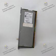
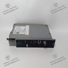
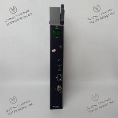
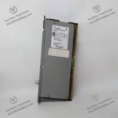
Product Description
I. Product Overview
The Allen - Bradley 1771 - ACN module is a ControlNet adapter module in the PLC 5 series.
This module features a compact and robust design, with dimensions of 3.5 x 6.5 x 2.0 inches (89 x 165 x 51 mm) and a weight of only 1.41 pounds (0.64 kg), making it easy to install in various industrial control cabinets and equipment racks. Its shell is made of high - quality industrial materials, boasting excellent anti - vibration and anti - impact performance. It can easily cope with the complex and changing environments of industrial sites, such as the strong equipment vibration in mechanical manufacturing workshops and the cargo collisions in logistics warehouses. This ensures that the module can operate stably under harsh conditions and guarantees the continuity and accuracy of data communication.

II. Performance Parameters
(1) Electrical Characteristics
Power requirements: It operates on 5 - volt direct current, with a backplane current of 1.0 ampere, a power consumption of 5 watts, and a heat dissipation of 17.06 British thermal units per hour. The stable and reasonable power requirements ensure that the module can continuously obtain sufficient and stable power support during long - term operation, guaranteeing the normal realization of various functions. At the same time, it effectively controls energy consumption and reduces operating costs.
Communication rate: It supports high - speed data transmission, with a transmission rate of up to 5 Mbps. This high rate enables rapid data interaction between devices. Whether it is production process control data with extremely high real - time requirements or a large amount of equipment status monitoring data, they can be transmitted quickly and accurately in the network, greatly improving the response speed and operational efficiency of the industrial automation system.
(2) Interface Characteristics
Control network interface: It is equipped with a standard BNC connector for connecting to the ControlNet network. Through this interface, the 1771 - ACN module can seamlessly communicate with other devices in the ControlNet network, such as PLC - 5 / 20C and PLC - 5 / 40C processors, realizing bidirectional data transmission and building a complete industrial automation control network.
Network Access Port (NAP): It has a NAP port in the form of an RJ - 48 8 - pin shielded connector. With this port, users can conveniently access the local communication network for programming, equipment debugging, and system maintenance, providing technicians with an efficient and convenient way to manage equipment.
(3) Environmental Adaptability
Operating temperature: It can operate stably within a temperature range of 0°C to 60°C (32°F to 140°F). This wide temperature adaptation range allows it to adapt to temperature changes in different industrial environments. Whether it is a production workshop in winter in cold regions, a factory building in summer in hot areas, or industries with special temperature requirements such as chemical industry and food processing, it can ensure the normal operation of the equipment and that communication is not affected by temperature fluctuations.
Storage temperature: In the storage state, it can withstand extreme temperatures ranging from - 40°C to 85°C (- 40°F to 185°F). This means that during equipment transportation, storage, and other links, even in harsh temperature conditions, the internal circuits and stored data of the module will not be damaged, effectively ensuring the reliability and stability of the equipment in various environments and reducing the risk of equipment failure due to environmental factors.

III. Functional Characteristics
(1) Efficient Data Interaction
Device communication bridge: The 1771 - ACN module can closely connect the 1771 series I/O modules with the PLC processor through the ControlNet network, realizing efficient data interaction between devices. In complex industrial automation production lines, it can collect data from various sensors, actuators, and other I/O devices in real - time, quickly transmit these data to the PLC processor for analysis and processing, and at the same time accurately convey the control instructions issued by the PLC to the corresponding I/O devices, achieving precise control of the production process.
Support for multiple data types: It can handle both discrete data, such as the on - off state of equipment and the start - stop signals of motors, and non - discrete data, such as analog temperature, pressure, and flow data. This ability to support multiple data types enables the module to adapt to data communication needs in different industrial scenarios, providing a strong guarantee for building a comprehensive and accurate industrial automation control system.
(2) Powerful Diagnostic Functions
Status display: The front of the module is equipped with an "OK" indicator light, a status indicator light, and an alphanumeric display. The "OK" indicator light can intuitively feedback the overall operating status of the module to the operator. It lights up during normal operation and turns off or flickers in case of a fault. The status indicator light can further display detailed information such as communication status and network connection status. The alphanumeric display can display various error codes and prompt information in real - time during equipment operation or initialization, helping technicians quickly locate and solve problems.
Communication reset button: When a communication failure occurs, pressing the communication reset button can quickly restore the module to a normal communication state. This function is extremely important in industrial production, as it can eliminate communication failures in the shortest time, reduce production downtime caused by communication interruptions, ensure the continuity and stability of the production process, and improve production efficiency.
(3) Flexible Address Configuration
Module network address setting: A module network address component is located on the top of the module, including a tens switch and a units switch. By properly setting these two switches, the network address of the module can be flexibly configured within the range of 1 - 99. This flexible address configuration method allows multiple 1771 - ACN modules to work together in the same ControlNet network without interfering with each other, facilitating users to reasonably layout and manage equipment according to the structure and needs of the actual industrial automation system.

IV. Installation and Use
(1) Installation Steps
Preparation before installation: Before installation, carefully check whether the appearance of the module is damaged and whether the accessories are complete. At the same time, ensure that the environment of the installation site meets the equipment requirements and avoid installation near strong electromagnetic interference sources and heat sources. Prepare the required installation tools, such as screwdrivers and wrenches, and be sure to cut off the power of all equipment connected to the module to ensure the safety of the installation process and prevent electric shock accidents.
Determine the installation location: The 1771 - ACN module should be installed in the leftmost slot of the 1771 I/O chassis. This is because its backplane connector is designed to only adapt to specific types of modules, and the electrical characteristics and signal transmission conditions of this position are most suitable for the module to exert its best performance. The installation location should be convenient for operators to observe the status of the module's indicator lights and for subsequent maintenance and repair work. At the same time, there should be sufficient space around the equipment to meet the heat dissipation and ventilation requirements, avoiding performance degradation or failure of the equipment due to poor heat dissipation.
Carry out the installation operation: According to the equipment marks, find the corresponding installation holes, and use supporting installation accessories such as screws and nuts to firmly install the module in the selected slot position. During the installation process, ensure that the installation is firm to avoid loosening of the module due to vibration and other factors, which may affect communication stability. Special attention should be paid to ensuring that the upper keyed band connector of the module is located between 54 - 56 frequency bands and the lower connector is located between 16 - 18 frequency bands during installation. The correct installation of the keyed band can effectively prevent incorrect modules from being inserted into the slot, ensuring the accuracy and reliability of equipment connection.
Connect cables: After fixing the module, connect the communication cables according to the system design. The 1771 - ACN module needs to be connected using a four - shielded RG - 6 coaxial cable. Connect the BNC plug at one end of the cable tightly to the BNC connector of the module to ensure a firm connection and good contact, avoiding signal transmission interruptions or interference caused by loosening or poor contact. After the connection is completed, check again whether the cable connections are correct and firm, and proceed to the next step only after confirmation.

(2) Usage Methods
Power - on and initialization: After completing the installation and checking that everything is correct, turn on the power of the equipment. The 1771 - ACN module will automatically perform the power - on initialization process. During this period, the module will conduct a comprehensive self - inspection of its own hardware and software, including key components such as internal circuits, communication interfaces, and memory chips. After the self - inspection is completed, the indicator lights on the front of the module will display corresponding status information. If the "OK" indicator light is on, it indicates that the equipment initialization is successful and can work normally; if the indicator light shows an abnormality or the alphanumeric display shows an error code, troubleshooting and repair should be carried out according to the prompts.
Network configuration and communication: Through the Network Access Port (NAP), use professional programming software to configure the network parameters of the module, such as setting the module's network address, communication rate, and subnet mask. After configuration, the module will automatically connect to the ControlNet network and establish communication connections with other devices in the network. During communication, the module will collect and transmit data in real - time, and operators can view information such as the operating status of the equipment and data transmission in real - time through monitoring software or a host computer to ensure stable communication and accurate data.
Equipment monitoring and maintenance: During the operation of the equipment, operators can monitor the operation of the module in real - time by observing the status of the indicator lights on the front of the module and the information on the alphanumeric display. If abnormalities are found, such as communication interruptions and error alarms, the problem can be quickly located according to the prompts of the indicator lights and the display. For some common faults, such as communication reset, they can be solved by pressing the communication reset button on the module; for more complex faults, professional diagnostic tools and technical knowledge are needed for in - depth troubleshooting and repair. At the same time, regularly cleaning the module and checking whether the cable connections are loose can effectively extend the service life of the equipment and ensure its stable operation.