

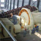
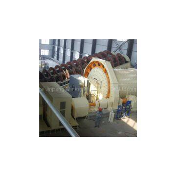
Dry Grinding Ball Mill
Negotiable
MOQ: 1 Piece (Price negotiable depending on order volume and customization)
Key Specifications
Get Latest Price
Brand Name:
Place of Origin:
China
Model Number:
Payment & Shipping
Payment Methods:
Port of Shipment:
China
Delivery Detail:
7 days
Related Products
Place of Origin
China
Ball millOperating instructionI. General Introduction for Ball Mill1. Structure:1. Feeder; 2. Feeding unit; 3. Discharging unit; 4. Cylinder;5. Girth gear; 6.Rack; 7. Transmission Division; 8. Bearing DivisionFig I Diagram of Ball MillAs shown in Fig I,Website: , the ball mill generally consists of eight parts: feeder, main bearing, feeding unit, cylinder, discharging unit, gear mechanism, gear cover, and foundation.As per the types of ball mills, they can be classified into overflow type (MQY type) and trellis type (MQG type).As per driving types of ball mills, they can be classified into dextrorotary type and laevorotatory type.As per modes of installing ball mills, they can be classified into with base plate type and without base plate type. With regards to ball mill with base plate, except an additional base plate, all the other parts are the same as those of ball mill without base plate. Below 15 series is with base plate.As per motor modes of ball mills, they can be classified into YR motor and JR motor. The structure difference between two types is the motor, the parts march to the motor and basement. The principle of two type marched is: to adopt YR motor when smaller than 80KW, to adopt JR motor when larger than 80KW.II. Installation of Ball Mill:1. Foundation of Ball Mill:① The foundation of ball mill is made of reinforced concrete. The foundation shall be solid and firm, and shall not sink. In case of slight sinkage, make sure to ensure consistent sinkage of each part of the foundation. Otherwise, it may exert negative effect upon normal working and operation of the ball mill.② Only relevant dimensions that can ensure correct installation of the ball mill are listed on the ball mill foundation drawing provided by us. The materials, structural design and peripheral dimensions of the foundation shall be determined according to geologic condition and other actual conditions of the user\'s installation site.2. General Precautions for Installation:① Before installation, check whether the foundation meets the requirements. Hole pitch of each anchor bolt on the foundation and permissible error of height mark of the foundation shall be in conformity with Table 1.Table 1 Hole pitch of each anchor bolt on the foundationand permissible error of height markHole Pitch L orHeight Mark H (㎜)Permissible Error (㎜)Dimensional deviation of relative position between height marks (㎜)≤500±11>500~1000±1.51.5≥1000±22② Check the quantity of the parts and components; check whether they are provided completely.③ Before installation, clean the surface of the parts and components, remove the burrs, rustings, foreign matters and oil stain.④ During installation, protect each coupling and fitting surface properly, apply clean lubricating oil onto each sliding matching surface, and apply clean lubricating grease to each fixed coupling surface. 3. Main parameter of the Ball Mill: Table 2modelCylinder diameterCylinder lengthRotary speedMotor modelMotor powerMotor speedEffective volumeMaximum load of ball090990090037.1Y180L-615KW9700.911.50918900180037.1Y200L-815KW7400.911.512281200280029.5YR280S-855KW7252.8515301500300029.8JR117-880KW72551021302100300024.05JR136-8180KW7359.01821362100360024JR137-8210KW7351121.621402100400024JR138-8245KW73512.123.524362400360022.5JR138-8A280KW743142624402400400022.5JR138-8B320KW743152624422400420022.5JR500L2-8355KW745162624452400450022.5JR500L3-8380KW7451729.527362700360021.6JR500L3-8380KW74519.436 4. Installation of the Ball Mill:A. Installation of rotating part: The parts such as feeder, charging unit, cylinder, girth gear, discharging unit and main bearing of the ball mill have been assembled prior to delivery, which constituting the rotating part of ball mill.① Put the lower part of gear cover at corresponding position on the foundation.② Put the anchor bolt of main bearing block into corresponding ground hole, unbolt the nut and gasket, etc. Put four groups of adjusting blocking iron onto the position of bed plate of each bearing block. While putting, make each group of blocking iron approach the hole of anchor bolt as close as possible and four groups of blocking iron be arranged as symmetrically as possible.③ Adjust the positions of bearing block and bed plate of bearing block.Loosened the Bolt before the bearing block and the bearing bed plate, adjust the adjustable bolts and nuts at both sides of bed plate of bearing block, to make longitudinal center of bed plate of bearing block coincide with the center of bearing block as much as possible.④ Lift the rotating part (please note: the casting lifting rings on charging and discharging end caps at both ends of ball mill shall be only used for lifting the end caps, and shall not be used for lifting the rotating part) and descend it gradually after spotting its location, to make axial diameter at both ends fall onto the corresponding Sizing Block. During the whereabouts of T-Anchor Bolt should be the lower part of the first card into the corresponding slots in Leong.⑤ Adjust radial position of bed plate of bearing:After the rotating part is lifted onto corresponding position, ensure that permissible error of parallelism between the center connection of bed plate of bearing block at both ends of ball mill and the ball mill center line lined out on the foundation ≤0.5/1000㎜ (designed on the basis of centers of two main bearings). Method of checking and adjusting: line out perpendicular line at the center of longitudinal end face of two bearing blocks, measure the distance between perpendicular line and center line of ball mill lined out on the foundation; in case of exceeding permissible error, lift the rotating part and re-install it.⑥ Adjust center height, radial and axial level and bearing block:After the bed plate of bearing block of rotating part is placed onto the foundation, find out correct center height of bearing block, radial and axial levels of bearing block synchronically and make them meet the following requirements:Permissible error of center height of bearing block ≤±4㎜; permissible error of levelness of bed plate of each bearing block ≤0.1/1000㎜. Measuring method: measure the levelness by placing the level meter in axial and radial directions at corresponding positions of bed plate of bearing block and the bearing.Permissible error of levelness of connection by axle center for two bearing blocks ≤0.2/1000㎜ (calculated on the basis of two bearing centers). Ensure that the discharging end is lower.⑦ After the position and level of both bearing block and bed plate of bearing block is adjusted and set properly, tighten the connecting bolts between bearing block and bed plate of bearing, and tighten the adjustable bolts and anchor bolts of bed plate of bearing block. And then, re-check the levelness at each position with the aforesaid method. In case of exceeding permissible error, loosen the anchor bolts and re-adjust them until the levelness at each position meets the requirements after tightening the anchor bolts.B. Installation of driving unitInstallation of this part includes installing such parts as pinion seat, reducer, motor, couplings, and gear cover, etc.① Put the anchor bolts of pinion seat, reducer and motor into corresponding holes on the foundation, and take off their nuts and gaskets. Place four groups of adjusting blocking iron on respective locating position of pinion seat, reducer and motor. While placing them, make each group of blocking iron approach the hole of anchor bolt as close as possible, and four groups of blocking iron be arranged as symmetrically as possible.② Cover high-speed and low-speed shaft ends of the reducer with high-speed and low-speed coupling casing. Put the pinion seat and the reducer and motor with base plate onto their positions respectively. And pull the anchor bolts through corresponding holes, and mount the gaskets and nuts.③ Adjust the positions and levels of pinion seat, reducer and motor synchronically, with the result of adjustment meet the following requirements:a. Permissible error of levelness of pinion shaft ≤0.1/1000㎜. And the deviation direction is consistent with the deviation direction of rotating part. Permissible error of parallelism between axial line of pinion and girth gear ≤0.1/1000㎜. Contact area when bull gear engages with the pinion ≥ 40% of tooth depth, ≥50% of face-width. In order to achieve the above mentioned requirements for engagement of pinion and girth gear, re-adjust the position of axial line of rotating part, if necessary. The gear backlash of bull gear engages with the pinion should meet the requirement of table 3.Table 3 Gear backlash of bull gear engages with the pinion Cylinder diameter(mm)Length of cylinder(mm)Gear backlash(mm)φ90018000.84~1.2φ120016002800φ150020000.84~1.230003500φ210024000.84~1.3300036004000φ240036000.84~1.4240004200φ270036000.84~1.424000 b. Permissible error of levelness of reducer and motor ≤0.1/1000㎜.Permissible error of coaxiality between pinion shaft and low-speed shaft of reducer ≤φ0.3.Permissible error of coaxiality between motor shaft and reducer shaft ≤0.3.④ After adjusting and leveling the position and level of each component of the driving unit properly, assemble the coupling of each component correctly.⑤ Assembling of gear cover:a. Adjustment before installing gear cover:For the deformed gear covers during transportation, shaping should be conducted prior to assembling, to meet requirements. Resetting of the sealing felt strip along the pinion shaft of gear cover, to make it available with a reliable sealing to pinion shaft after assembling.b. Assembling of gear cover:Foreign objects and oil on the bull gear and pinion before assembling of gear cover should be well cleaned before locating the lower-cover of gear as required. Check the assembling clearances and sealing clearances at each spot to ensure that sealings are in good conditions as required before fixing the upper cover of gear. Check now the assembling clearance and sealing condition of gear cover at each spot to ensure full compliance. In case of complete compliance, tighten all the bolts of gear cover.c. Grouting of anchor bolt holes of foundation and tightening of anchor bolts:After installation and adjustment of all the above parts, grouting of sandstone and concrete grout can be conducted into each anchor bolt hole as required. Please note that for anchor bolt holes of main bearing seat without ground beam and pinion seat, to ensure a grouting till bottom for ground beam, check again the installation requirements at each place as per instructions above after concrete mortar in each anchor bolt hole is fully dried. If any change or unconformity is found, make further micro adjustment till installation at each place reach requirements and then tighten each anchor bolts at each spot to finish the installation.5. Precautions for Installation of Each Part of Ball Mill:① Lead paint should be applied between end cover of loading/unloading and drum flange face when making assembling. However, spacer is prohibited.②Rolling bearing inner ring and feeding cover journal and discharging journal cover for light Journal cover fit (P7 with) the application of heat bearing assembly installed law. When the bearing assembly can be placed in the oil, with oil heated to about

Send Inquiry to This Supplier

* Email
Want the best price?
Post an RFQ now!
Business Type
Trading Company
Total Employees
101 - 200 People
Main Markets
North America, South America, Eastern Europe
Location
Lishui, Zhejiang, China
You May Also Like
-
 German AVENTICS 0822241932 Cylinder is New and OriginalNegotiableMOQ: 1 Piece
 -
Quality Steel Cord Fabric 3×0.2+6×0.35HT Used in Elevator Belt, Enhance the Lateral Resistant Copper Woven Mesh Fabric 3×4×0.22HE/US$ 1 - 200MOQ: 10 Kilometers
-
Grass Hand Tooth Sickle Steel Gardening/Agricultural Tools Sickle for AfricaNegotiableMOQ: 1 Piece
-
Fisherman Fishing Use Double Sides Multifunctional WhetstoneNegotiableMOQ: 1000 Pieces
-
Other Hydraulic ComponentsNegotiableMOQ: 2600 Sets
-
300W Industrial Thermostatic Type Glue Gun Hot Glue Gun Temperature Adjustment Hot Melt Glue GunUS$ 2.22MOQ: 1 Kilogram
-
Heavy Duty Long Blade Machete Knife High Carbon Steel Survival Machete for Outdoor Farming UseNegotiableMOQ: 1200 Pieces
-
Stainless Steel Bending Spring Plumbing Tool Zinc Extension Furniture Industrial UseUS$ 0.1 - 9.99MOQ: 100 Pieces
-
BECKETT Plastic Square Packaging TubesUS$ 0.13 - 0.17MOQ: 5000 Pieces
-
SANDVIK CNC Cutting Insert TNMG 27 06 16-PR 4415 for High-Speed MachiningNegotiableMOQ: 10 Blades
